ISO 32000-1 Document management — Portable document format — Part 1: PDF 1.7 - page 14

Table 298 - Additional entries specific to a 3D annotation (continued)
Key
Type
Value
3DB
rectangle
(Optional) The 3D view box, which is the rectangular area in which the 3D
artwork shall be drawn. It shall be within the rectangle specified by the
annotation’s Rect entry and shall be expressed in the annotation’s target
coordinate system (see discussion following this Table).
Default value: the annotation’s Rect entry, expressed in the target
coordinate system. This value is [ -w/2 -h/2 w/2 h/2 ], where w and h are
the width and height, respectively, of Rect.
The 3DB entry specifies the 3D view box, a rectangle in which the 3D artwork appears. The view box shall fit
within the annotation’s rectangle (specified by its Rect entry). It may be the same size, or it may be smaller if
necessary to provide extra drawing area for additional 2D graphics within the annotation.
NOTE 1
Although 3D artwork can internally specify viewport size, conforming readers ignore it in favour of information
provided by the 3DB entry.
The view box shall be specified in the annotation’s target coordinate system, whose origin is at the center of the
annotation’s rectangle. Units in this coordinate system are the same as default user space units. Therefore, the
coordinates of the annotation’s rectangle in the target coordinate system are
[ -w/2 -h/2 w/2 h/2 ]
given w and h as the rectangle’s width and height.
The 3DD entry shall specify a 3D stream that contains the 3D artwork to be shown in the annotation; 3D
streams are described in Section 13.6.3. The 3DD entry may specify a 3D stream directly; it may also specify a
3D stream indirectly by means of a 3D reference dictionary (see 13.6.3.3, "3D Reference Dictionaries"). These
options control whether annotations shall share the same run-time instance of the artwork.
The 3DV entry shall specify the view of the 3D artwork that is displayed when the annotation is activated (as
described in the next paragraph). 3D views, which are described in Section 13.6.4, represent settings for the
virtual camera, such as position, orientation, and projection style. The view specified by 3DV shall be one of the
3D view dictionaries listed in the VA entry in a 3D stream (see Table 300).
The 3DA entry shall be an activation dictionary (see Table 299) that determines how the state of the annotation
and its associated artwork may change.
NOTE 2
These states serve to delay the processing or display of 3D artwork until a user chooses to interact with it.
Such delays in activating 3D artwork can be advantageous to performance.
At any given moment, a 3D annotation shall be in one of two states:
•
Inactive (the default initial state): the annotation displays the annotation’s normal appearance.
NOTE 3
It is typical, though not required, for the normal appearance to be a pre-rendered bitmap of the default view of
the 3D artwork. Conforming writers should provide bitmaps of appropriate resolution for all intended uses of
the document; for example, a high-resolution bitmap for high-quality printing and a screen-resolution bitmap for
on-screen viewing. Optional content (see 8.11, “Optional Content”) may be used to select the appropriate
bitmap for each situation.
•
Active: the annotation displays a rendering of the 3D artwork. This rendering shall be specified by the
annotation’s 3DV entry.
513

Table 299 - Entries in a 3D activation dictionary
Key
Type
Value
A
name
(Optional) A name specifying the circumstances under which the
annotation shall be activated. Valid values are:
PO The annotation shall be activated as soon as the page containing
the annotation is opened.
PV The annotation shall be activated as soon as any part of the page
containing the annotation becomes visible.
XA The annotation shall remain inactive until explicitly activated by a
script or user action.
NOTE 1
At any one time, only a single page shall be considered
open in a conforming reader, even though more than one
page may be visible, depending on the page layout.
Default value: XA.
NOTE 2
For performance reasons, documents intended for viewing
in a web browser should use explicit activation (XA). In non-
interactive applications, such as printing systems or
aggregating conforming reader, PO and PV indicate that the
annotation shall be activated when the page is printed or
placed; XA indicates that the annotation shall never be
activated and the normal appearance shall be used.
AIS
name
(Optional) A name specifying the state of the artwork instance upon
activation of the annotation. Valid values are:
I
The artwork shall be instantiated, but real-time script-driven
animations shall be disabled.
L Real-time script-driven animations shall be enabled if present; if
not, the artwork shall be instantiated.
Default value: L.
NOTE 3
In non-interactive conforming readers, the artwork shall be
instantiated and scripts shall be disabled.
D
name
(Optional) A name specifying the circumstances under which the
annotation shall be deactivated. Valid values are:
PC The annotation shall be deactivated as soon as the page is closed.
PI The annotation shall be deactivated as soon as the page
containing the annotation becomes invisible.
XD The annotation shall remain active until explicitly deactivated by a
script or user action.
NOTE 4
At any one time, only a single page shall be considered
open in the conforming reader, even though more than one
page may be visible, depending on the page layout.
Default value: PI.
DIS
name
(Optional) A name specifying the state of the artwork instance upon
deactivation of the annotation. Valid values are U (uninstantiated), I
(instantiated), and L (live). Default value: U.
NOTE 5
If the value of this entry is L, uninstantiation of instantiated
artwork is necessary unless it has been modified.
Uninstantiation is never required in non-interactive
conforming readers.
514

Table 299 - Entries in a 3D activation dictionary (continued)
Key
Type
Value
TB
boolean
(Optional; PDF
1.7) A flag indicating the default behavior of an
interactive toolbar associated with this annotation. If true, a toolbar shall
be displayed by default when the annotation is activated and given
focus. If false, a toolbar shall not be displayed by default.
NOTE 6
Typically, a toolbar is positioned in proximity to the
3D
annotation.
Default value: true.
NP
boolean
(Optional; PDF 1.7) A flag indicating the default behavior of the user
interface for viewing or managing information about the 3D artwork.
Such user interfaces can enable navigation to different views or can
depict the hierarchy of the objects in the artwork (the model tree). If true,
the user interface should be made visible when the annotation is
activated. If false, the user interface should not be made visible by
default.
Default value: false
The A and D entries of the activation dictionary determine when a 3D annotation may become active and
inactive. The AIS and DIS entries determine what state the associated artwork shall be in when the annotation
is activated or deactivated. 3D artwork may be in one of three states:
•
Uninstantiated: the initial state of the artwork before it has been used in any way.
•
Instantiated: the state in which the artwork has been read and a run-time instance of the artwork has been
created. In this state, it may be rendered but script-driven real-time modifications (that is, animations) shall
be disabled.
•
Live: the artwork has been instantiated, and it is being modified in real time to achieve some animation
effect. In the case of keyframe animation, the artwork shall be live while it is playing and then shall revert to
an instantiated state when playing completes or is stopped.
NOTE 4
The live state is valid only for keyframe animations or in interactive conforming readers that have JavaScript
support.
If
3D artwork becomes uninstantiated after having been instantiated, later use of the artwork requires re-
instantiation (animations are lost, and the artwork appears in its initial form).
NOTE 5
For this reason, uninstantiation is not necessary unless the artwork has been modified in some way;
consumers may choose to keep unchanged artwork instantiated for performance reasons.
NOTE 6
In non-interactive systems such as printing systems, the artwork cannot be changed. Therefore, applications
may choose to deactivate annotations and uninstantiate artwork differently, based on factors such as memory
usage and the time needed to instantiate artwork, and the TB, NP, D and DIS entries may be ignored.
Multiple 3D annotations may share an instance of 3D artwork, as described in 13.6.3.3, "3D Reference
Dictionaries". In such a case, the state of the artwork instance shall be determined in the following way:
•
If any active annotation dictates (through its activation dictionary) that the artwork shall be live, it shall be
live.
•
Otherwise, if any active annotation dictates that the artwork shall be instantiated, it shall be instantiated.
•
Otherwise (that is, all active annotations dictate that the artwork shall be uninstantiated), the artwork shall
be uninstantiated.
515

The rules described in 13.6.2, “3D Annotations”, apply only to active annotations. If all annotations referring to
the artwork are inactive, the artwork nevertheless may be uninstantiated, instantiated, or live 3D Streams.
13.6.3
3D Streams
13.6.3.1
General
The specification of 3D artwork shall be contained in a 3D stream. 3D stream dictionaries, whose entries (in
addition to the regular stream dictionary's entries; see 7.3.7, “Dictionary Objects”) are shown in Table 300, may
provide a set of predefined views of the artwork, as well as a default view. They may also provide scripts and
resources for providing customized behaviours or presentations.
Table 300 - Entries in a 3D stream dictionary
Key
Type
Value
Type
name
(Optional) The type of PDF object that this dictionary describes; if
present, shall be 3D for a 3D stream.
Subtype
name
(Required) A name specifying the format of the 3D data contained in
the stream. The only valid value is U3D.
VA
array
(Optional) An array of 3D view dictionaries, each of which specifies a
named preset view of this
3D artwork (see Section
13.6.4,
“3D
Views”).
DV
(various)
(Optional) An object that specifies the default (initial) view of the 3D
artwork. It may be a 3D view dictionary (see Section 13.6.4, “3D
Views”) or one of the following types:
•
An integer specifying an index into the VA array.
•
A text string matching the IN entry in one of the views in the VA
array.
•
A name that indicates the first (F) or last (L) entries in the VA
array.
Default value: 0 (the first entry in the VA array) if VA is present; if VA is
not present, the default view shall be specified within the 3D stream
itself.
Resources
name tree
(Optional) A name tree that maps name strings to objects that may be
used by applications or scripts to modify the default view of the 3D
artwork.
The names in this name tree shall be text strings so as to be encoded
in a way that will be accessible from JavaScript.
OnInstantiate
stream
(Optional) A JavaScript script that shall be executed when the 3D
stream is instantiated.
AN
dictionary
(Optional; PDF
1.7) An animation style dictionary indicating the
method that conforming readers should use to drive keyframe
animations present in this artwork (see 13.6.3.2, "3D Animation Style
Dictionaries").
Default value: an animation style dictionary whose Subtype entry has
a value of None.
The Subtype entry specifies the format of the 3D stream data. The only valid value is U3D, which indicates that
the stream data conforms to the Universal 3D File Format specification (see Bibliography). Conforming readers
shall be prepared to encounter unknown values for Subtype and recover appropriately, which usually means
leaving the annotation in its inactive state, displaying its normal appearance.
NOTE
Conforming readers should follow the approach of falling back to the normal appearance with regard to entries
in other dictionaries that may take different types or values than the ones specified here.
516

If present, the VA entry shall be an array containing a list of named present views of the 3D artwork. Each entry
in the array shall be a 3D view dictionary (see 13.6.4, “3D Views”) that shall contain the name of the view and
the information needed to display the view. The order of array elements determines the order in which the
views shall be presented in a user interface. The DV entry specifies the view that shall be used as the initial
view of the 3D artwork.
Default views shall be determined in the following order of precedence: in the annotation dictionary, in the 3D
stream dictionary, or in the 3D artwork contained in the 3D stream.
3D streams contain information that may be used by conforming readers and by scripts to perform animations
and other programmatically-defined behaviours, such as changing the viewing orientation or moving individual
components of the artwork. If present, the OnInstantiate entry shall contain a JavaScript script that shall be
executed by applications that support JavaScript whenever a 3D stream is read to create an instance of the 3D
artwork. The Resources entry shall be a name tree that contains objects that may be used to modify the initial
appearance of the 3D artwork.
13.6.3.2
3D Animation Style Dictionaries
A 3D animation style dictionary (PDF 1.7) specifies the method that conforming readers should use to apply
timeline scaling to keyframe animations. It may also specify that keyframe animations be played repeatedly.
The AN entry of the 3D stream shall specify a 3D animation style dictionary.
A keyframe animation may be provided as the content of a 3D stream dictionary. A keyframe animation
provides key frames and specifies the mapping for the position of geometry over a set period of time (animation
timeline). Keyframe animation is an interactive feature that is highly dependent on the behaviour and controls
provided by the conforming reader.
Table 301 shows the entries in an animation style dictionary.
Table 301 - Entries in an 3D animation style dictionary
Key
Type
Value
Type
name
(Optional). The type of PDF object that this dictionary describes; if present,
shall be 3DAnimationStyle.
Subtype
name
(Optional) The animation style described by this dictionary; see Table 302
for valid values. If an animation style is encountered other than those
described in Table 302, an animation style of None shall be used.
Default value: None
PC
integer
(Optional) An integer specifying the play count for this animation style. A
non-negative integer represents the number of times the animation shall
be played. A negative integer indicates that the animation shall be infinitely
repeated. This value shall be ignored for animation styles of type None.
Default value: 0
TM
number
(Optional) A positive number specifying the time multiplier to be used
when running the animation. A value greater than one shortens the time it
takes to play the animation, or effectively speeds up the animation.
NOTE
This allows authors to adjust the desired speed of animations,
without having to re-author the 3D artwork.
This value shall be ignored for animation styles of type None.
Default value: 1
The descriptions of the animation styles (see Table 302) use the following variables to represent application
time or keyframe settings specified in the 3D artwork.
517

•
t is a point on the animation time line. This value shall be used in conjunction with the keyframe animation
data to determine the state of the 3D artwork.
•
[r0, r1] is the keyframe animation time line.
•
t
a is the current time of the conforming reader.
•
t
0 is the time when the conforming reader starts the animation.
•
p is the time it takes to play the keyframe animation through one cycle. In the case of the Linear animation
style, one cycle consists of playing the animation through once from beginning to end. In the case of the
Oscillating animation style, one cycle consists of playing the animation from beginning to end and then
from end to beginning.
•
m is the positive multiplier specified by the TM entry in the animation style dictionary.
Table 302 - Animation styles
None
Keyframe animations shall not be driven directly by the conforming
reader. This value shall be used by documents that are intended to
drive animations through an alternate means, such as JavaScript.
The remaining entries in the animation style dictionary shall be
ignored.
Linear
Keyframe animations shall be driven linearly from beginning to end.
This animation style results in a repetitive playthrough of the
animation, such as in a walking motion.
t = (m(ta - t0) + r0) % (r1 - r0)
p = (r1 - r0) / m
The “%” symbol indicates the modulus operator.
Oscillating
Keyframe animations shall oscillate along their time range. This
animation style results in a back-and-forth playing of the animation,
such as exploding or collapsing parts.
t = (0.5)(r1 - r0)(1 - cos(m(ta - t0))) + r0
p = 2 * pi / m
13.6.3.3
3D Reference Dictionaries
More than one 3D annotation may be associated with the same 3D artwork. There are two ways in which this
association may occur, as determined by the annotation’s 3DD entry (see Table 298):
•
If the 3DD entry specifies a 3D stream, the annotation shall have its own run-time instance of the 3D
artwork. Any changes to the artwork shall be reflected only in this annotation. Other annotations that refer
to the same stream shall have separate run-time instances.
•
If the 3DD entry specifies a 3D reference dictionary (whose entries are shown in Table 303), the annotation
shall have a run-time instance of the 3D artwork with all other annotations that specify the same reference
dictionary. Any changes to the artwork shall be reflected in all such annotations.
518

Table 303 - Entries in a 3D reference dictionary
Key
Type
Value
Type
name
(Optional) The type of PDF object that this dictionary describes; if
present, shall be 3DRef for a 3D reference dictionary.
3DD
stream
(Required) The 3D stream (see 13.6.3, “3D Streams”) containing the
specification of the 3D artwork.
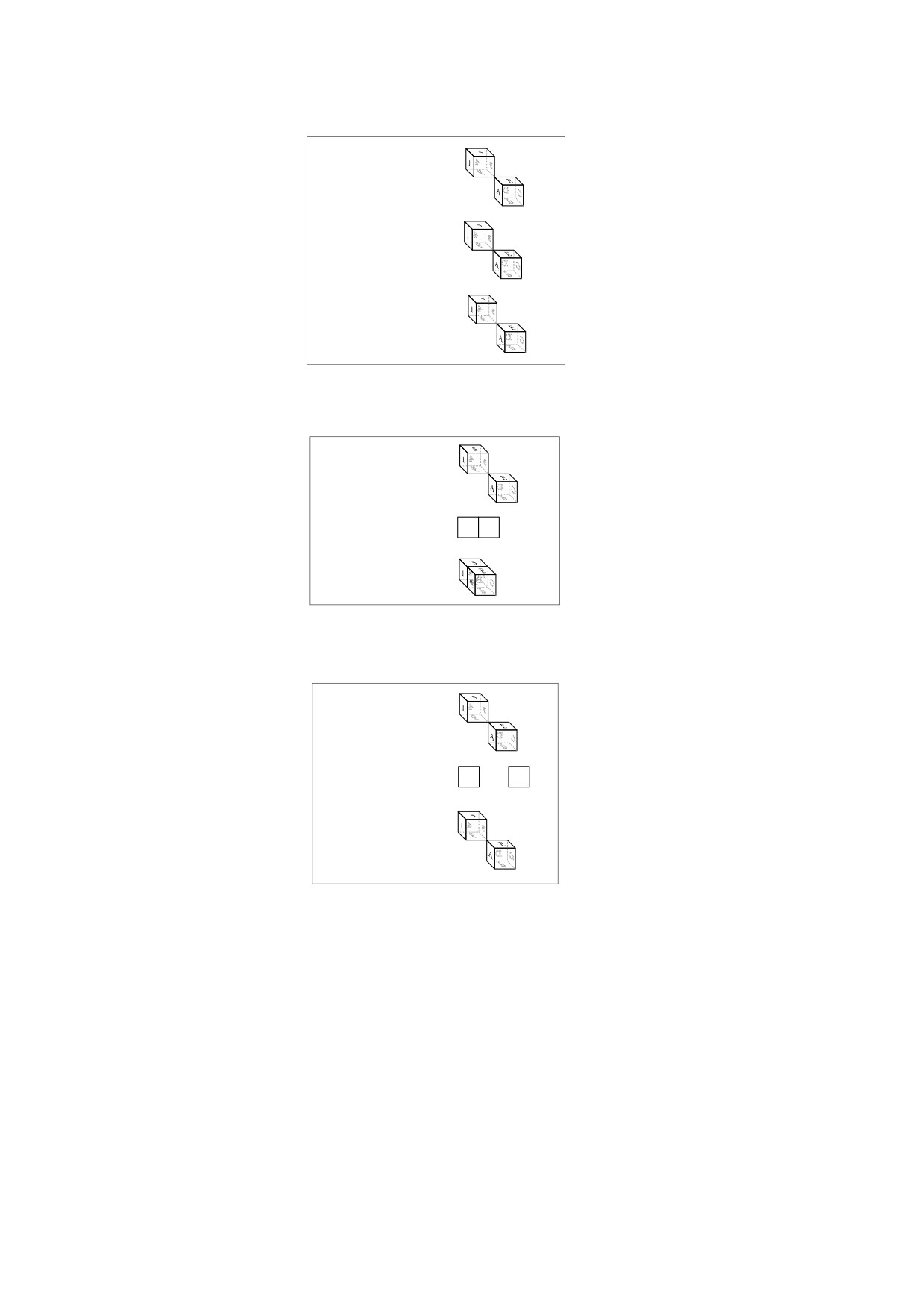
EXAMPLE
The following example and Figure 66 through Figure 68 show three annotations that use the same 3D
artwork. Object 100 (Annotation 1) has its own run-time instance of the 3D stream (object 200); object
101(Annotation 2) and object 102 (Annotation 3) share a run-time instance through the 3D reference
dictionary (object 201).
100 0 obj
% 3D annotation 1
<< /Type /Annot
/Subtype /3D
/3DD 200 0 R
% Reference to the 3D stream containing the 3D artwork
>>
endobj
101 0 obj
% 3D annotation 2
<< /Type /Annot
/Subtype /3D
/3DD 201 0 R
% Reference to a 3D reference dictionary
>>
endobj
102 0 obj
% 3D annotation 3
<< /Type /Annot
/Subtype /3D
/3DD 201 0 R
% Reference to the same 3D reference dictionary
>>
endobj
200 0 obj
% The 3D stream
<< /Type /3D
/Subtype /U3D
... other keys related to a stream, such as /Length
>>
stream
... U3D data...
endstream
endobj
201 0 obj
% 3D reference dictionary
<< /Type /3DRef
/3DD 200 0 R
% Reference to the actual 3D artwork.
>>
endobj
519
2
Annotation 1
B
2
Annotation 2
B
2
Annotation 3
B
Figure 66 - Default view of artwork
2
Annotation 1
B
Annotation 2
1
A
Annotation 3
B
Figure 67 - Annotation 2 rotated
2
Annotation 1
B
Annotation 2
1
A
2
Annotation 3
B
Figure 68 - Shared artwork (annotations 2 & 3) modified
The figures show how the objects in the Example in 13.5, “Alternate Presentations,” might be used.
Figure 66 shows the same initial view of the artwork in all three annotations. Figure 67 shows the results
of rotating the view of the artwork within Annotation 2. Figure 68 shows the results of manipulating the
artwork shared by Annotation 2 and Annotation 3: they both reflect the change in the artwork because
they share the same run-time instance. Annotation 1 remains unchanged because it has its own run-time
instance.
NOTE
When multiple annotations refer to the same instance of 3D artwork, the state of the instance is determined as
described in 13.6.2, “3D Annotations.”
520

13.6.4
3D Views
13.6.4.1
General
A 3D view (or simply view) specifies parameters that shall be applied to the virtual camera associated with a 3D
annotation. These parameters may include orientation and position of the camera, details regarding the
projection of camera coordinates into the annotation’s target coordinate system, and a description of the
background on which the artwork shall be drawn. Starting with PDF 1.7, views may specify how 3D artwork is
rendered, coloured, lit, and cross-sectioned, without the use of embedded JavaScript. Views may also specify
which nodes (three-dimensional areas) of 3D artwork shall be included in a view and whether those nodes are
opaque or invisible.
NOTE 1
Users can manipulate views by performing interactive operations such as free rotation and translation. In
addition, 3D artwork can contain a set of predefined views that the author deems to be of particular interest.
For example, a mechanical drawing of a part may have specific views showing the top, bottom, left, right, front,
and back of an object.
A 3D stream may contain a list of named preset views of the 3D artwork, as specified by the VA entry, which
shall be an array of 3D view dictionaries. The entries in a 3D view dictionary are shown in Table 304.
Table 304 - Entries in a 3D view dictionary
Key
Type
Value
Type
name
(Optional) The type of PDF object that this dictionary describes; if
present, shall be 3DView for a 3D view dictionary.
XN
text string
(Required) The external name of the view, suitable for presentation in a
user interface.
IN
text string
(Optional) The internal name of the view, used to refer to the view from
other objects, such as the go-to-3D-view action (see 12.6.4.15, “Go-To-
3D-View Actions”).
MS
name
(Optional) A name specifying how the
3D camera-to-world
transformation matrix shall be determined. The following values are
valid:
M Indicates that the C2W entry shall specify the matrix
U3D Indicates that the view node selected by the U3DPath entry shall
specify the matrix.
If omitted, the view specified in the 3D artwork shall be used.
C2W
array
(Required if the value of MS is M, ignored otherwise) A 12-element 3D
transformation matrix that specifies a position and orientation of the
camera in world coordinates.
U3DPath
text string
or
(Required if the value of MS is U3D, ignored otherwise) A sequence of
array
one or more text strings used to access a view node within the 3D
artwork. The first string in the array is a node ID for the root view node,
and each subsequent string is the node ID for a child of the view node
specified by the prior string. Each view node specifies a
3D
transformation matrix (see 13.6.5, “Coordinate Systems for 3D”); the
concatenation of all the matrices forms the camera-to-world matrix.
Conforming writers should specify only a single text string, not an array,
for this entry.
NOTE
Do not confuse View Nodes with nodes. A View Node is a
parameter in the 3D artwork that specifies a view, while a
node is a PDF dictionary that specifies 3D graphic objects
or collections thereof.
521

Table 304 - Entries in a 3D view dictionary (continued)
Key
Type
Value
CO
number
(Optional; used only if MS is present) A non-negative number indicating
a distance in the camera coordinate system along the z axis to the center
of orbit for this view; see discussion following this Table. If this entry is
not present, the conforming reader shall determine the center of orbit.
P
dictionary
(Optional) A projection dictionary (see 13.6.4.2, “Projection Dictionaries”)
that defines the projection of coordinates in the 3D artwork (already
transformed into camera coordinates) onto the target coordinate system
of the annotation.
Default value: a projection dictionary where the value of Subtype is
Perspective, the value of FOV is 90, and all other entries take their
default values.
O
stream
(Optional; meaningful only if MS and P are present) A form XObject that
shall be used to overlay 2D graphics on top of the rendered 3D artwork
(see 13.6.6, “3D Markup”).
BG
dictionary
(Optional) A background dictionary that defines the background over
which the 3D artwork shall be drawn (see 13.6.4.3, “3D Background
Dictionaries”). Default value: a background dictionary whose entries take
their default values.
RM
dictionary
(Optional; PDF 1.7) A render mode dictionary that specifies the render
mode to use when rendering 3D artwork with this view (see 13.6.4.4, “3D
Render Mode Dictionaries”). If omitted, the render mode specified in the
3D artwork shall be used.
LS
dictionary
(Optional; PDF 1.7) A lighting scheme dictionary that specifies the
lighting scheme to be used when rendering 3D artwork with this view
(see 13.6.4.5, “3D Lighting Scheme Dictionaries”). If omitted, the lighting
scheme specified in the 3D artwork shall be used.
SA
array
(Optional; PDF 1.7) An array that contains cross section dictionaries
(see 13.6.4.6,
“3D Cross Section Dictionaries”). Each cross section
dictionary provides parameters for applying a cross section to the 3D
artwork when using this view. An empty array signifies that no cross
sections shall be displayed.
NA
array
(Optional; PDF 1.7; meaningful only if NR is present) An array that
contains 3D node dictionaries (see 13.6.4.7, “3D Node Dictionaries”).
Each node dictionary may contain entries that change the node’s state,
including its opacity and its position in world space. This entry and the
NR entry specify how the state of each node shall be changed.
If a node dictionary is present more than once, only the last such
dictionary (using a depth-first traversal) shall be used.
NR
boolean
(Optional; PDF 1.7) Specifies whether nodes specified in the NA array
shall be returned to their original states (as specified in the 3D artwork)
before applying transformation matrices and opacity settings specified in
the node dictionaries. If true, the artwork’s 3D node parameters shall be
restored to their original states and then the dictionaries specified by the
NA array shall be applied. If false, the dictionaries specified by the NA
array shall be applied to the current states of the nodes.
In addition to the parameters specified by a 3D node dictionary, this flag
should also apply to any runtime parameters used by a conforming
reader.
Default value: false
For any view, the conforming writer may provide 2D content specific to the view, to be drawn on top of the 3D
artwork. The O entry specifies a form XObject that shall be overlaid on the rendered 3D artwork. The
522
coordinate system of the form XObject shall be defined to be the same as the (x, y, 0) plane in the camera
coordinate system (see 13.6.5, “Coordinate Systems for 3D”).
Use of the O entry is subject to the following restrictions.
NOTE 2
Failure to abide by them could result in misalignment of the overlay with the rendered 3D graphics:
• It may be specified only in 3D view dictionaries in which both a camera-to-world matrix (MS
and associated entries) and a projection dictionary (the P entry) are present.
• The form XObject shall be associated with a specific view (not with the camera position de-
fined by the 3D view dictionary). The conforming reader should draw it only when the user
navigates using the 3D view, not when the user happens to navigate to the same orientation
by manual means.
• The confirming reader should draw it only if the user has not invoked any actions that alter the
artwork-to-world matrix.
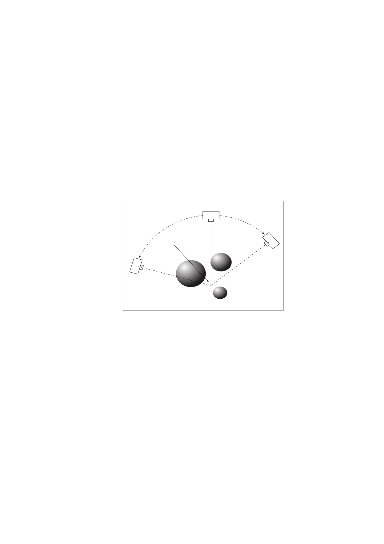
The CO entry specifies the distance from the camera to the center of orbit for the 3D view, which is the point
around which the camera shall rotate when performing an orbit-style navigation. Figure 69 illustrates camera
positioning when orbiting around the center of orbit.
Center Of Orbit
Figure 69 - Rotation around the center of orbit
NOTE 3
The LS entry allows the lighting of the 3D artwork to be changed without changing the artwork itself. This
enables consumers to view a given piece of 3D artwork with a variety of lighting options without requiring
multiple copies of the 3D artwork stream that differ only in lighting. It also enables artwork with poor lighting to
be corrected in cases where the original content cannot be re-authored. See 13.6.4.5, “3D Lighting Scheme
Dictionaries.”
The SA entry provides cross section information for clipping 3D artwork while its associated view is active. This
allows view authors to be more clear in calling out the intended areas of interest for a particular view, some of
which might otherwise be completely obscured. See 13.6.4.6, “3D Cross Section Dictionaries.”
The NR and NA entries are meant to give a more accurate representation of the 3D artwork at a given state.
These keys give view authors finer granularity in manipulating the artwork to be presented in a particular way.
They also provide a means for returning node parameters to a known state after potential changes by
interactive features such as keyframe animations and JavaScript. See 13.6.4.7, “3D Node Dictionaries.”
13.6.4.2
Projection Dictionaries
A projection dictionary (see Table 305) defines the mapping of 3D camera coordinates onto the target
coordinate system of the annotation. Each 3D view may specify a projection dictionary by means of its P entry.
NOTE
Although view nodes can specify projection information, PDF consumers ignore it in favour of information in
the projection dictionary.
523

PDF 1.6 introduces near/far clipping. This type of clipping defines a near plane and a far plane (as shown in
Figure 70). Objects, or parts of objects, that are beyond the far plane or closer to the camera than the near
plane are not drawn. 3D objects shall be projected onto the near plane and then scaled and positioned within
the annotation’s target coordinate system, as described Table 305.
Table 305 - Entries in a projection dictionary
Key
Type
Value
Subtype
name
(Required) The type of projection. Valid values shall be O (orthographic) or P
(perspective).
CS
name
(Optional) The clipping style. Valid values shall be XNF (explicit near/far) or ANF
(automatic near/far). Default value: ANF.
F
number
(Optional; meaningful only if the value of CS is XNF) The far clipping distance,
expressed in the camera coordinate system. No parts of objects whose z
coordinates are greater than the value of this entry are drawn. If this entry is
absent, no far clipping occurs.
N
number
(Meaningful only if the value of CS is XNF; required if the value of Subtype is P)
The near clipping distance, expressed in the camera coordinate system. No
parts of objects whose z coordinates are less than the value of this entry are
drawn. If Subtype is P, the value shall be positive; if Subtype is O, the value
shall be non-negative, and the default value is 0.
FOV
number
(Required if Subtype is P, ignored otherwise) A number between 0 and 180,
inclusive, specifying the field of view of the virtual camera, in degrees. It defines
a cone in 3D space centered around the z axis and a circle where the cone
intersects the near clipping plane. The circle, along with the value of PS, specify
the scaling of the projected artwork when rendered in the 2D plane of the
annotation.
PS
number
(Optional; meaningful only if Subtype is P) An object that specifies the scaling
or name
used when projecting the 3D artwork onto the annotation’s target coordinate
system. It defines the diameter of the circle formed by the intersection of the near
plane and the cone specified by FOV. The value may be one of the following:
•
A positive number that explicitly specifies the diameter as a distance in the
annotation’s target coordinate system.
•
A name specifying that the diameter shall be set to the width (W), height
(H), minimum of width and height (Min), or maximum of width and height
(Max) of the annotation’s 3D view box.
Default value: W.
OS
number
(Optional; meaningful only if Subtype is O) A positive number that specifies the
scale factor to be applied to both the x and y coordinates when projecting onto
the annotation’s target coordinate system (the z coordinate is discarded). Default
value: 1.
OB
name
(Optional; PDF 1.7; meaningful only if Subtype is O) A name that specifies a
strategy for binding (scaling to fit) the near plane’s x and y coordinates onto the
annotation’s target coordinate system. The scaling specified in this entry shall be
applied in addition to the scaling factor specified by the OS entry. The value may
be one of the following:
W
Scale to fit the width of the annotation
H
Scale to fit the height of the annotation
Min
Scale to fit the lesser of width or height of the annotation
Max
Scale to fit the greater of width or height of the annotation
Absolute No scaling should occur due to binding.
Default value: Absolute.
524
The CS entry defines how the near and far planes are determined. A value of XNF means that the N and F
entries explicitly specify the z coordinate of the near and far planes, respectively. A value of ANF for CS means
that the near and far planes shall be determined automatically based on the objects in the artwork.
The Subtype entry specifies the type of projection, which determines how objects are projected onto the near
plane and scaled. The possible values are O for orthographic projection and P for perspective projection.
For orthographic projection, objects shall be projected onto the near plane by simply discarding their z value.
They shall be scaled from units of the near plane’s coordinate system to those of the annotation’s target
coordinate system by the combined factors specified by the OS entry and the OB entry.
For perspective projection, a given coordinate (x, y, z) shall be projected onto the near plane, defining a 2D
coordinate (x1, y1) using the following formulas:
=
x× --
x1
z
=
y× --
y1
z
where n is the z coordinate of the near plane.
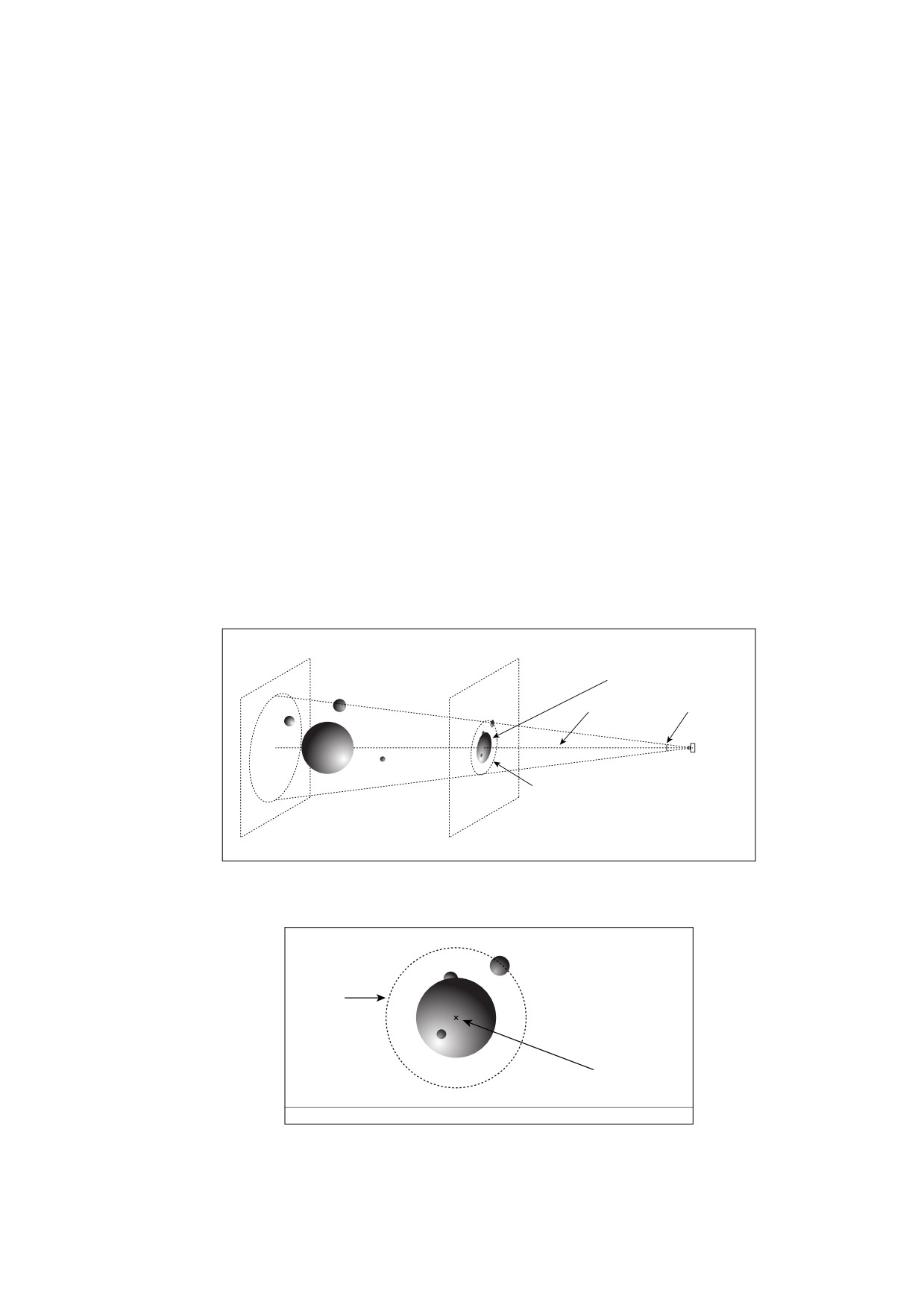
Scaling with perspective projection is more complicated than for orthographic projection. The FOV entry
specifies an angle that defines a cone centered along the z axis in the camera coordinate system (see Figure
70). The cone intersects with the near plane, forming a circular area on the near plane. Figure 71 shows this
circle and graphics from the position of the camera.
Far Clipping Plane
Near Clipping plane
Objects projected onto near clipping plane
Z axis
Field of View angle
Circle defined by Field of View angle on near clipping plane
Figure 70 - Perspective projection of 3D artwork onto the near plane
FOV circle
Z axis projected onto near plane
Figure 71 - Objects projected onto the near clipping plane, as seen from the position of the camera
525
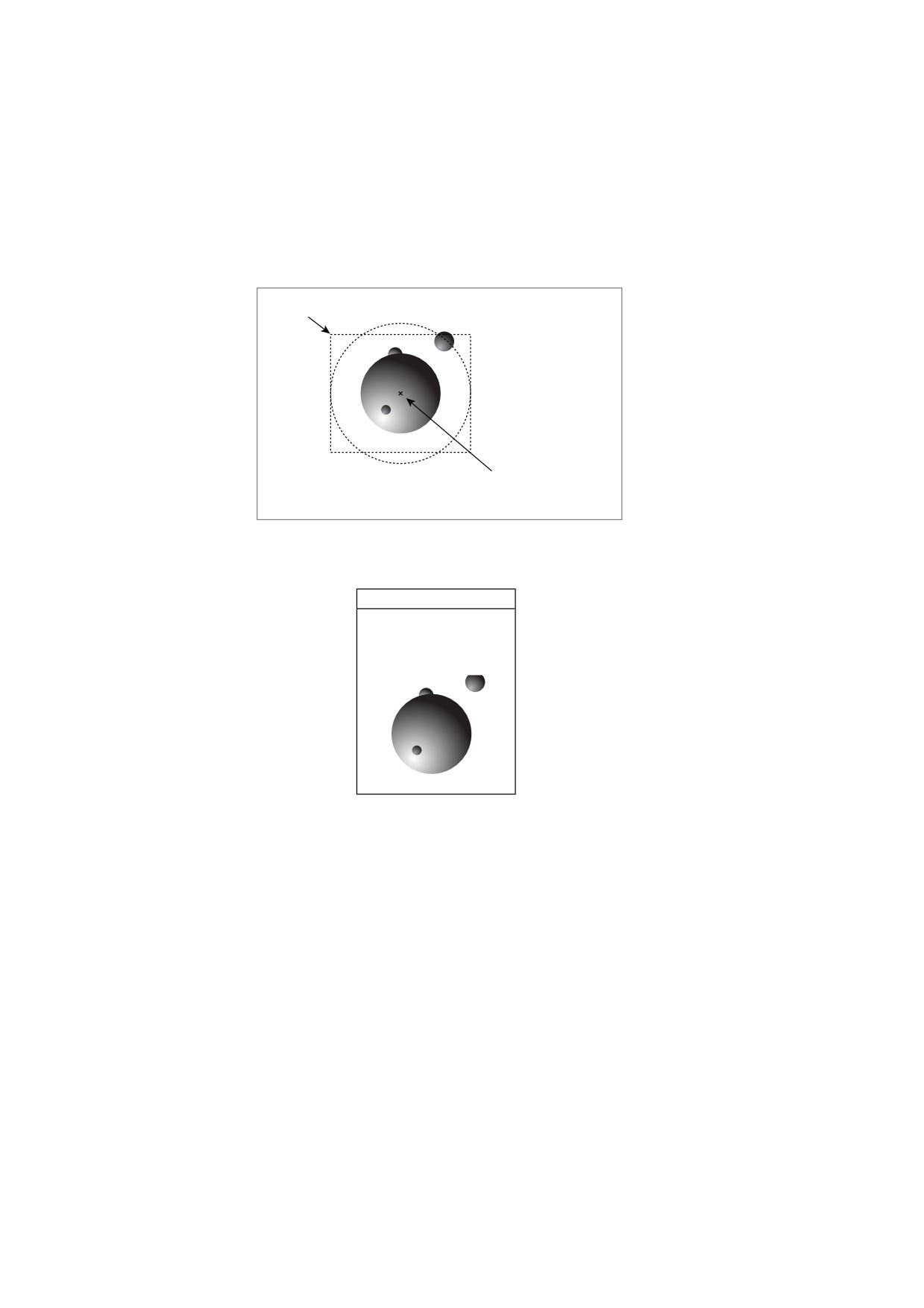
The PS entry specifies the diameter that this circle will have when the graphics projected onto the near plane
are rendered in the annotation’s 3D view box (see Figure 72). Although the diameter of the circle determines
the scaling factor, graphics outside the circle shall also be displayed, providing they fit within the view box, as
seen in the figure.
Figure 73 shows the entire 3D annotation. In this case, the 3D view box is smaller than the annotation’s
rectangle, which also contains 2D content outside the 3D view box.
3D Annotation’s 3DB box
Z axis projected onto near plane,
aligned with center of 3DB box,
scaled to fit the width of the 3DB box
Figure 72 - Positioning and scaling the near plane onto the annotation’s 3D view box
The Daily News
New Planet
Discovered!
Figure 73 - 3D annotation positioned on the page
13.6.4.3
3D Background Dictionaries
A 3D background dictionary defines the background over which a 3D view shall be drawn.Table 306 shows the
entries in a background dictionary. Currently, only a single opaque colour is supported, where the colour shall
be defined in the DeviceRGB colour space. 3D artwork may include transparent objects; however, there is no
interaction between such objects and objects drawn below the annotation. In effect, the 3D artwork and its
background form a transparency group whose flattened results have an opacity of 1 (see 11, “Transparency”).
NOTE
An annotation’s normal appearance should have the same behaviour with respect to transparency when the
appearance is intended to depict the 3D artwork. This does not apply when the appearance is used for another
purpose, such as a compatibility warning message.
526
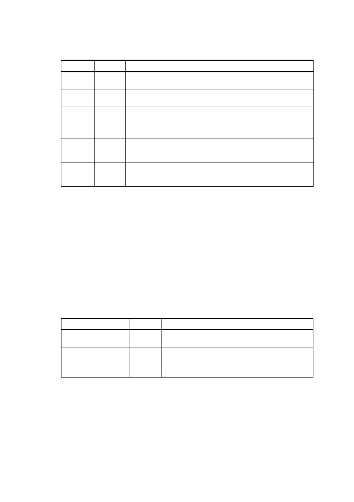
Table 306 - Entries in a 3D background dictionary
Key
Type
Value
Type
name
(Optional) The type of PDF object that this dictionary describes; if present,
shall be 3DBG for a 3D background dictionary.
Subtype
name
(Optional) The type of background. The only valid value shall be SC (solid
colour), which indicates a single opaque colour. Default value: SC.
CS
name or
(Optional) The colour space of the background. The only valid value shall be
array
the name DeviceRGB. Default value: DeviceRGB.
PDF consumers shall be prepared to encounter other values that may be
supported in future versions of PDF.
C
(various)
(Optional) The colour of the background, in the colour space defined by CS.
Default value: an array [1 1 1] representing the colour white when the value
of CS is DeviceRGB.
EA
boolean
(Optional) If true, the background shall apply to the entire annotation; if
false, the background shall apply only to the rectangle specified by the
annotation’s 3D view box (the 3DB entry in Table 298). Default value: false.
13.6.4.4
3D Render Mode Dictionaries
A 3D render mode dictionary (PDF 1.7) specifies the style in which the 3D artwork shall be rendered.
NOTE 1
Surfaces may be filled with opaque colours, they may be stroked as a “wireframe,” or the artwork may be
rendered with special lighting effects.
NOTE 2
A render mode dictionary enables document authors to customize the rendered appearance of 3D artwork to
suit the needs of the intended consumer, without reauthoring the artwork. For conforming readers concerned
strictly with geometry, complex artwork rendered using the Wireframe or Points style may have much better
performance without the added overhead of texturing and lighting effects. Artwork in a document intended for
print may have a much more integrated feel when using the Illustration render mode style.
The RM entry in the 3D views dictionary may specify a 3D render mode dictionary.
Table 307 shows the entries in a render mode dictionary.
Table 307 - Entries in a render mode dictionary
Key
Type
Value
Type
name
(Optional) The type of PDF object that this dictionary
describes; if present, shall be 3DRenderMode.
Subtype
name
(Required) The type of render mode described by this
dictionary; see Table 308 for specific values. If an
unrecognized value is encountered, then this render mode
dictionary shall be ignored.
527

Table 307 - Entries in a render mode dictionary (continued)
Key
Type
Value
AC
array
(Optional) An array that specifies the auxiliary colour that
shall be used when rendering the 3D image. The first entry in
the array shall be a colour space; the subsequent entries
shall be values specifying colour values in that colour space.
The interpretation of this entry depends on the render mode
specified by the Subtype entry, but it is often used to specify
a colour for drawing points or edges.
The only valid colour space shall be DeviceRGB. If a colour
space other than DeviceRGB is specified, this entry shall be
ignored and the default value shall be used.
Default value: [/DeviceRGB 0 0 0] representing the colour
black.
FC
name
or
(Optional) A name or array that specifies the face color to be
array
used when rendering the 3D image. This entry shall be
relevant only when Subtype has a value of Illustration.
If the value of FC is an array, the first entry in the array shall
be a colour space and the subsequent entries shall be values
specifying values in that colour space. The only valid colour
space is DeviceRGB. Any colour space other than
DeviceRGB shall be ignored and the default value shall be
used.
If the value of FC is a name, it shall describe a colour. The
only valid name value shall BG, specifying the current
background colour in use for displaying the artwork. If a name
other than BG is encountered, this entry shall be ignored and
the background colour for the host annotation shall be used
(see Table 189).
Default value: BG
O
number
(Optional) A number specifying the opacity of the added
transparency applied by some render modes, using a
standard additive blend.
Default value: 0.5
CV
number
(Optional) A number specifying the angle, in degrees, that
shall be used as the crease value when determining
silhouette edges. If two front-facing faces share an edge and
the angle between the normals of those faces is greater than
or equal to the crease value, then that shared edge shall be
considered a silhouette edge.
Default value: 45
For render modes that add a level of transparency to the rendering, the O entry specifies the additional opacity
that shall be used. All such transparency effects use a standard additive blend mode.
The CV entry sets the crease value that shall be used when determining silhouette edges, which may be used
to adjust the appearance of illustrated render modes. An edge shared by two faces shall be considered a
silhouette edge if either of the following conditions is met:
•
One face is front-facing and the other is back-facing.
•
The angle between the two faces is greater than or equal to the crease value.
528

Table 308 describes the render modes that may be specified in a render mode dictionary.
Table 308 - Render modes
Mode
Description
Solid
Displays textured and lit geometric shapes. In the case of artwork
that conforms to the Universal 3D File Format specification, these
shapes are triangles. The AC entry shall be ignored.
SolidWireframe
Displays textured and lit geometric shapes (triangles) with single
colour edges on top of them. The colour of these edges shall be
determined by the AC entry.
Transparent
Displays textured and lit geometric shapes (triangles) with an
added level of transparency. The AC entry shall be ignored.
TransparentWireframe
Displays textured and lit geometric shapes (triangles) with an
added level of transparency, with single colour opaque edges on
top of it. The colour of these edges shall be determined by the AC
entry.
BoundingBox
Displays the bounding box edges of each node, aligned with the
axes of the local coordinate space for that node. The colour of the
bounding box edges shall be determined by the AC entry.
TransparentBoundingBox
Displays bounding boxes faces of each node, aligned with the
axes of the local coordinate space for that node, with an added
level of transparency. The colour of the bounding box faces shall
be determined by the FC entry.
TransparentBoundingBoxOutline
Displays bounding boxes edges and faces of each node, aligned
with the axes of the local coordinate space for that node, with an
added level of transparency. The colour of the bounding box
edges shall be determined by the AC entry. The colour of the
bounding boxes faces shall be determined by the FC entry.
Wireframe
Displays only edges in a single colour. The colour of these edges
shall be determined by the AC entry.
ShadedWireframe
Displays only edges, though interpolates their colour between
their two vertices and applies lighting. The AC entry shall be
ignored.
HiddenWireframe
Displays edges in a single colour, though removes back-facing
and obscured edges. The colour of these edges shall be
determined by the AC entry.
Vertices
Displays only vertices in a single colour. The colour of these points
shall be determined by the AC entry.
ShadedVertices
Displays only vertices, though uses their vertex colour and applies
lighting. The AC entry shall be ignored.
Illustration
Displays silhouette edges with surfaces, removes obscured lines.
The colour of these edges shall be determined by the AC entry,
and the colour of the surfaces shall be determined by the FC
entry.
SolidOutline
Displays silhouette edges with lit and textured surfaces, removes
obscured lines. The colour of these edges shall be determined by
the AC entry.
ShadedIllustration
Displays silhouette edges with lit and textured surfaces and an
additional emissive term to remove poorly lit areas of the artwork.
The colour of these edges shall be determined by the AC entry.
529
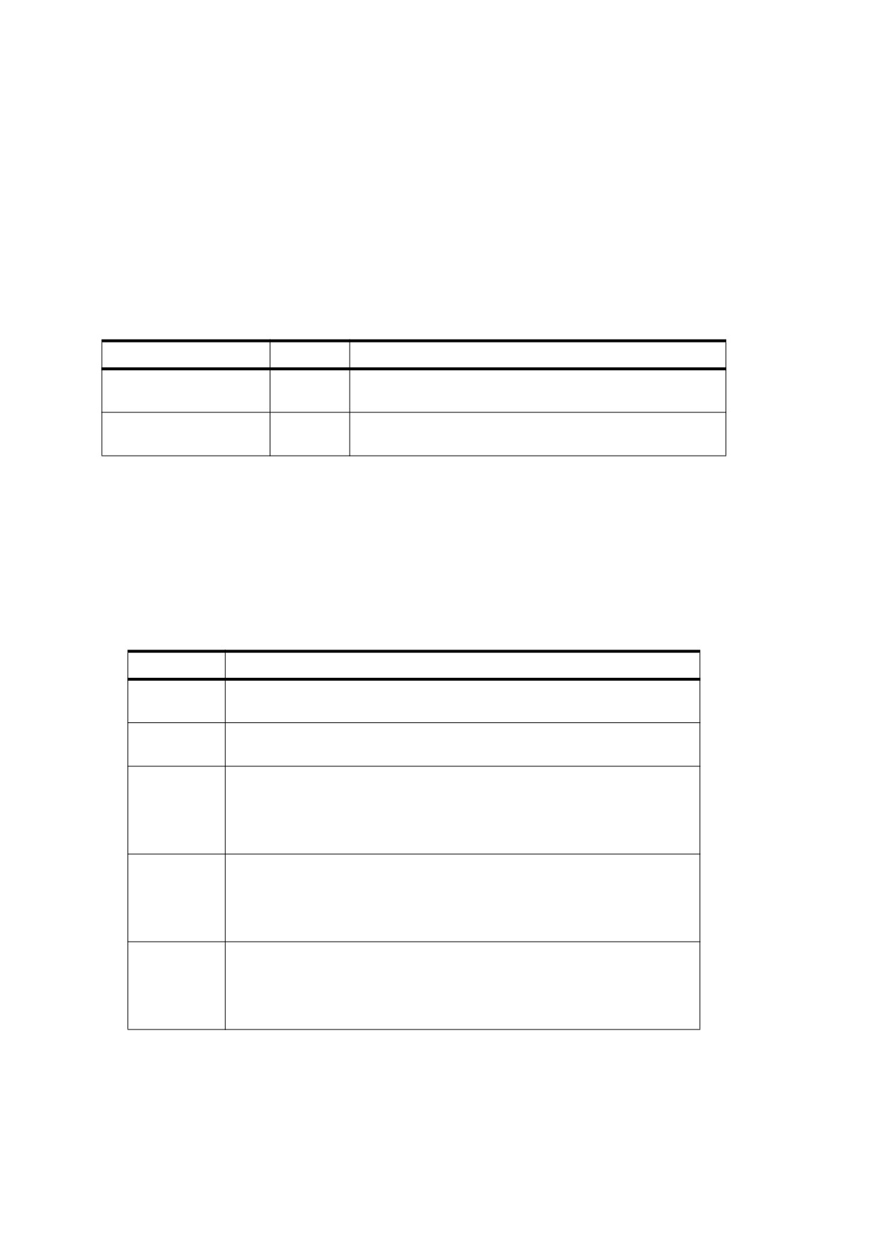
If a render mode type is encountered other than those described in Table 308, the render mode dictionary
containing that entry shall be ignored by its consumers. This allows future documents using new render modes
to behave consistently with future documents using new 3D view constructs that are ignored by older viewers.
13.6.4.5
3D Lighting Scheme Dictionaries
A 3D lighting scheme dictionary (PDF 1.7) specifies the lighting to apply to 3D artwork. The LS entry in the 3D
view may include a 3D lighting scheme dictionary.
Table 301 shows the entries in a 3D lighting scheme dictionary.
Table 309 - Entries in a 3D lighting scheme dictionary
Key
Type
Value
Type
name
(Optional) The type of PDF object that this dictionary
describes; if present, shall be 3DLightingScheme.
Subtype
name
(Required) The style of lighting scheme described by this
dictionary (see Table 310).
Table 310 describes the supported lighting schemes. With the exception of the Artwork lighting style, all the
lights specified in Table 310 are infinite lights (also known as distant lights). Unlike lights from a point source, all
rays from an infinite light source are emitted along a single direction vector. For lights specifying an ambient
term, this term shall be added to the diffuse colour of an object’s material. All colours shall be specified in the
DeviceRGB colour space.
When a style other than Artwork is used, only those lights described shall be present; any lighting described in
the artwork shall not be used.
Table 310 - 3D lighting scheme styles
Scheme
Description
Artwork
Lights as specified in the 3D artwork. This has the same effect as if the 3D
lighting scheme dictionary were omitted.
None
No lights shall be used. That is, lighting specified in the 3D artwork shall be
ignored.
White
Three blue-grey infinite lights, no ambient term
Light 1
Colour: < 0.38, 0.38, 0.45 > Direction: < -2.0, -1.5, -0.5 >
Light 2
Colour: < 0.6, 0.6, 0.67 > Direction: < 2.0, 1.1, -2.5 >
Light 3
Colour: < 0.5, 0.5, 0.57 > Direction: < -0.5, 0.0, 2.0 >
Day
Three light-grey infinite lights, no ambient term
Light 1
Colour: < 0.5, 0.5, 0.5 >
Direction: < -2.0, -1.5, -.5 >
Light 2
Colour: < 0.8, 0.8, 0.9 >
Direction: < 2.0, 1.1, -2.5 >
Light 3
Colour: < 0.9, 0.9, 0.9 >
Direction: < 0.02, 0.01, 2.0 >
Night
One yellow, one aqua, and one blue infinite light, no ambient term
Light 1
Colour: < 1, .75, .39 >
Direction: < -2.0, -1.5, -0.5 >
Light 2
Colour: < 0.31, 0.47, 0.55 > Direction: < 2.0, 1.1, -2.5 >
Light 3
Colour: < .5, .5, 1.0 >
Direction: < 0.0, 0.0, 2.0 >
530

Table 310 - 3D lighting scheme styles (continued)
Scheme
Description
Hard
Three grey infinite lights, moderate ambient term
Light
Colour: < 0.5, 0.5, 0.5 > Direction: < -1.5, -1.5, -1.5 >
Light 2
Colour: < 0.8, 0.8, 0.9 > Direction: < 1.5, 1.5, -1.5 >
Light 3
Colour: < 0.9, 0.9, 0.9 > Direction: < -0.5, 0, 2.0 >
Ambient Colour: < 0.5, 0.5, 0.5 >
Primary
One red, one green, and one blue infinite light, no ambient term
Light 1
Colour: < 1, 0.2, 0.5 >
Direction: < -2, -1.5, -0.5 >
Light 2
Colour: < 0.2, 1.0, 0.5 >
Direction: < 2.0, 1.1, -2.5 >
Light 3
Colour: < 0, 0, 1 >
Direction: < 0.0, 0.0, 2.0 >
Blue
Three blue infinite lights, no ambient term
Light 1
Colour: < 0.4, 0.4, 0.7 >
Direction: < -2.0, -1.5, -0.5 >
Light 2
Colour: < 0.75, 0.75, 0.95 > Direction: < 2.0, 1.1, -2.5 >
Light 3
Colour: < 0.7, 0.7, 0.95 > Direction: < 0.0, 0.0, 2.0 >
Red
Three red infinite lights, no ambient term
Light 1
Colour: < 0.8, 0.3, 0.4 >
Direction: < -2.0, -1.5, -0.5 >
Light 2
Colour: < 0.95, 0.5, 0.7 > Direction: < 2.0, 1.1, -2.5 >
Light 3
Colour: < 0.95, 0.4, 0.5 > Direction: < 0.0, 0.0, 2.0 >
Cube
Six grey infinite lights aligned with the major axes, no ambient term
Light 1
Colour: < .4, .4, .4 >
Direction: < 1.0, 0.01, 0.01 >
Light 2
Colour: < .4, .4, .4 >
Direction: < 0.01, 1.0, 0.01 >
Light 3
Colour: < .4, .4, .4 >
Direction: < 0.01, 0.01, 1.0 >
Light 4
Colour: < .4, .4, .4 >
Direction: < -1.0, 0.01, 0.01 >
Light 5
Colour: < .4, .4, .4 >
Direction: < 0.01, -1.0, 0.01 >
Light 6
Colour: < .4, .4, .4 >
Direction: < 0.01, 0.01, -1.0 >
CAD
Three grey infinite lights and one light attached to the camera, no ambient
term
Light 1
Colour: < 0.72, 0.72, 0.81 > Direction: < 0.0, 0.0, 0.0 >
Light 2
Colour: < 0.2, 0.2, 0.2 >
Direction: < -2.0, -1.5, -0.5 >
Light 3
Colour: < 0.32, 0.32, 0.32 > Direction: < 2.0, 1.1, -2.5 >
Light 4
Colour: < 0.36, 0.36, 0.36 > Direction: < 0.04, 0.01, 2.0 >
Headlamp
Single infinite light attached to the camera, low ambient term
Light 1
Colour: < 0.8, 0.8, 0.9 >
Direction: < 0.0, 0.0, 0.0 >
Ambient Colour: < 0.1, 0.1, 0.1 >
NOTE
If a lighting scheme style is encountered other than those described in Table 310, the lighting scheme
dictionary containing that entry shall be ignored. This allows future documents using new lighting schemes to
behave consistently with future documents using new 3D view constructs. That is, the expected behaviour is
for the conforming reader to ignore unrecognized lighting styles and 3D view constructs.
13.6.4.6
3D Cross Section Dictionaries
A 3D cross section dictionary (PDF 1.7) specifies how a portion of the 3D artwork shall be clipped for the
purpose of showing artwork cross sections. The SA entry of a 3D view may specify multiple 3D cross section
dictionaries.
531

NOTE
Cross sections enable conforming readers to display otherwise hidden parts of the artwork. They also allow
users to comment on cross sections, using markup annotations. For example, markup annotations can be
used to apply markup annotations to a cross section or to measure distances in a cross section. If multiple
cross sections are specified for a view, the markup annotations in the view apply to all cross sections in the
view.
Table 311 shows the entries in a 3D cross section dictionary.
Table 311 - Entries in a 3D cross section dictionary
Key
Type
Value
Type
name
(Optional) The type of PDF object that this dictionary describes; if present, shall
be 3DCrossSection for a 3D cross section dictionary.
C
array
(Optional) A three element array specifying the center of rotation on the cutting
plane in world space coordinates (see 13.6.5, “Coordinate Systems for 3D”).
Default value: [0 0 0] specifying a cutting plane rotating about the origin of the
world space.
O
array
(Required) A three-element array specifying the orientation of the cutting plane
in world space, where each value represents the orientation in relation to the X,
Y, and Z axes, respectively (see 13.6.5, “Coordinate Systems for 3D”). Exactly
one of the values shall be null, indicating an initial state of the cutting plane
that is perpendicular to the corresponding axis and clipping all geometry on the
positive side of that axis. The other two values shall be numbers indicating the
rotation of the plane, in degrees, around their corresponding axes. The order in
which these rotations are applied shall match the order in which the values
appear in the array.
Default value: [null 0 0] specifying a cutting plane that is perpendicular to the X
axis and coplanar with the Y and Z axes.
PO
number
(Optional) A number in the range [0, 1] indicating the opacity of the cutting
plane using a standard additive blend mode.
Default value: 0.5
PC
array
(Optional) An array that specifies the colour for the cutting plane. The first entry
in the array is a colour space, and the remaining entries are values in that
colour space. The only valid colour space is DeviceRGB. If a colour space
other than DeviceRGB is specified, this entry shall be ignored and the default
value shall be used.
Default value: [/DeviceRGB 1 1 1] representing the colour white.
IV
boolean
(Optional) A flag indicating the visibility of the intersection of the cutting plane
with any 3D geometry. If true, then the intersection shall be visible. If false,
then the intersection shall not be visible.
Default value: false
IC
array
(Optional) An array that specifies the colour for the cutting plane’s intersection
with the 3D artwork. The first entry in the array is a colour space, and the
remaining entries are values in that colour space. The only valid colour space
is DeviceRGB. If a colour space other than DeviceRGB is specified, this entry
shall be ignored and the default value shall be used. This entry is meaningful
only if IV is true.
Default value: [/DeviceRGB 0 1 0] representing the colour green.
The C entry specifies the center of the cutting plane. This implies that the plane passes through the center
point, but it is also the point of reference when determining the orientation of the plane.
The O array indicates the orientation of the cutting plane, taking into account its center. The orientation may be
determined by a two-step process:
532
•
The plane shall be situated such that it passes through point C, and oriented such that it is perpendicular to
the axis specified by the array entry whose value is null.
•
For each of the other two axes, the plane shall be rotated the specified number of degrees around the
associated axis, while maintaining C as a fixed point on the plane. Since the two axes are perpendicular,
the order in which the rotations are performed is irrelevant.
The PO entry specifies the opacity of the plane itself when rendered, while the PC entry provides its colour.
When the PO entry is greater than 0, a visual representation of the cutting plane shall be rendered with the 3D
artwork. This representation is a square with a side length equal to the length of the diagonal of the maximum
bounding box for the 3D artwork, taking into account any keyframe animations present. When the PO entry is
0, no visible representation of the cutting plane shall be rendered.
The IV entry shall be a boolean value that determines whether a visual indication shall be drawn of the plane’s
intersection with the 3D artwork. If such an indication is drawn, the IC entry shall specify its colour.
EXAMPLE
The following example describes a set of views and corresponding cross sections that illustrate the
various effects of orientation.
3 0 obj
%CrossSection1
<<
/Type /3DCrossSection
/C [0 0 0]
/O [null 0 0]
/PO 0.35
/PC [/DeviceRGB 0.75 0.86 1]
/IV true
/IC [/DeviceRGB 0 1 0]
>>
endobj
4 0 obj
%CrossSection2
<<
/Type /3DCrossSection
/C [0 0 0]
/O [null -30 0]
/PO 0.35
/PC [/DeviceRGB 0.75 0.86 1]
/IV true
/IC [/DeviceRGB 0 1 0]
>>
endobj
5 0 obj
%CrossSection3
<<
/Type /3DCrossSection
/C [0 0 0]
/O [null 0 30]
/PO 0.35
/PC [/DeviceRGB 0.75 0.86 1]
/IV true
/IC [/DeviceRGB 0 1 0]
>>
endobj
6 0 obj
%CrossSection4
<<
/Type /3DCrossSection
533
/C [0 0 0]
/O [null -30 30]
/PO 0.35
/PC [/DeviceRGB 0.75 0.86 1]
/IV true
/IC [/DeviceRGB 0 1 0]
>>
endobj
7 0 obj
%View0
<<
/Type /3DView
/XN (NoCrossSection)
/SA []
>>
endobj
8 0 obj
%View1
<<
/Type /3DView
/XN (CrossSection1)
/SA [3 0 R]
>>
endobj
9 0 obj
%View2
<<
/Type /3DView
/XN (CrossSection2)
/SA [4 0 R]
>>
endobj
10 0 obj
%View3
<<
/Type /3DView
/XN (CrossSection3)
/SA [5 0 R]
>>
endobj
11 0 obj
%View4
<<
/Type /3DView
/XN (CrossSection4)
/SA [6 0 R]
>>
endobj
The following illustrations show the views described in the previous example, some of which include cross
sections.
534
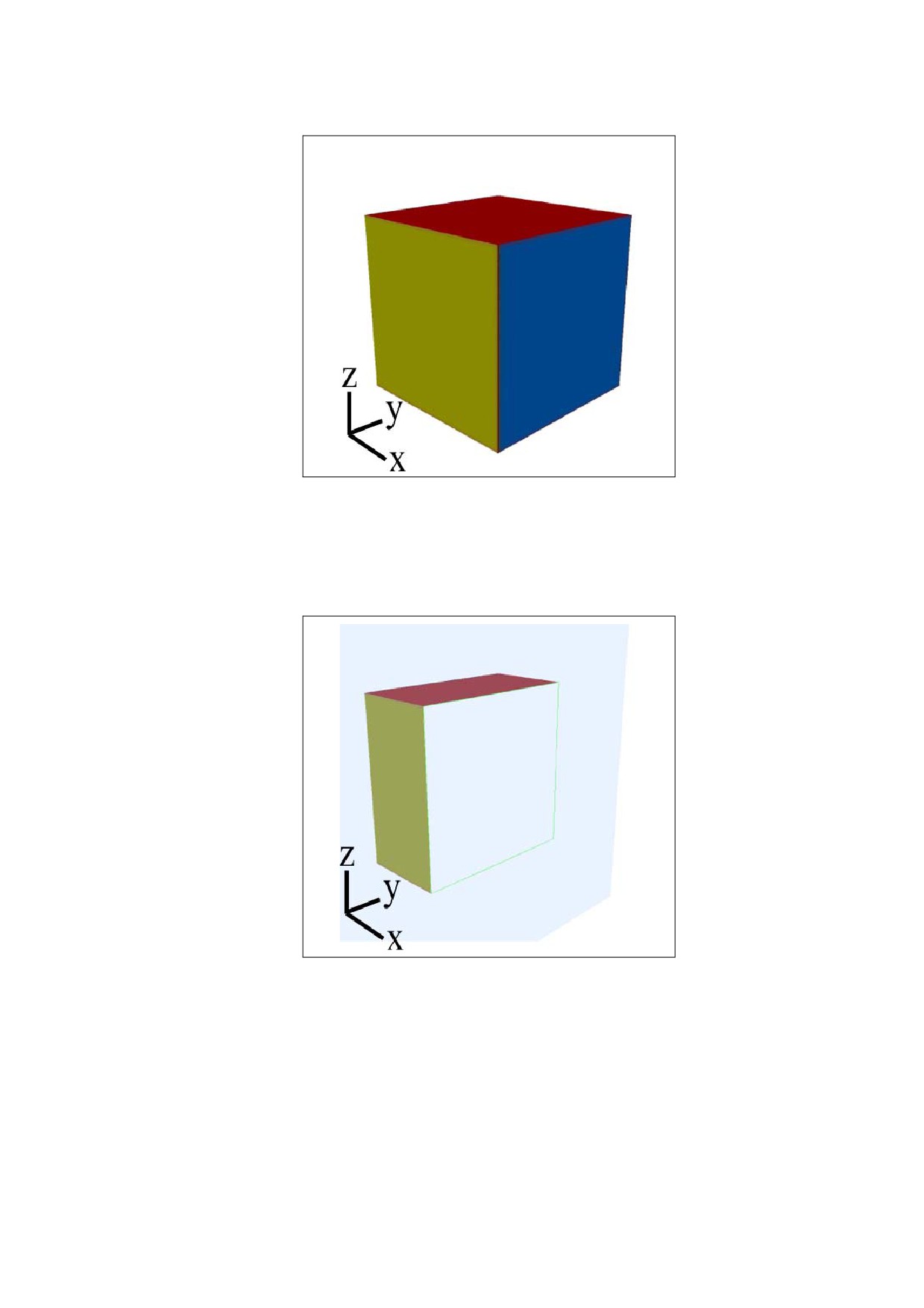
Figure 74 - Rendering of the 3D artwork using View0 (no cross section)
Figure 74 through Figure 78 use world coordinates whose origin is the center of the cube. The axes illustrated
in each diagram show the relative orientation of the world coordinate axes, not the actual position of those
axes. These axes are not part of the 3D artwork used in this example.
Figure 75 - Rendering of the 3D artwork using View1
(cross section perpendicular to the x axis)
Figure 75 shows the cross section specified for the 3DView that references CrossSection1. The illustration
shows the edges of the cutting plane ending at the edges of the annotation’s rectangle. This cross section
specifies a plane with the following characteristics:
•
Includes the world art origin: /C [0 0 0]
•
Perpendicular to the X axis and parallel to the Y and Z axes: /O [ null 0 0]
•
Opacity of the cutting plane is 35%: /PO 0.35
535
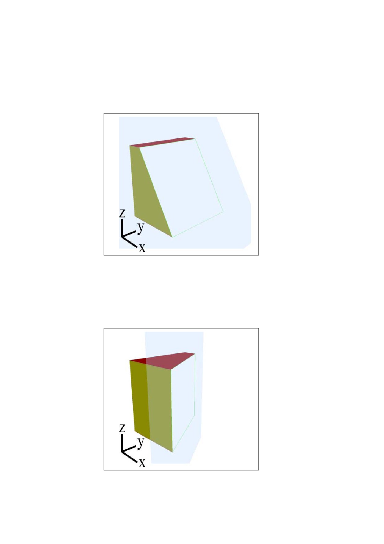
•
Colour of the cutting plane is light blue: /PC [/DeviceRGB 0.75 0.86 1]
•
Intersection of the cutting plane with the object is visible: /IV true
•
Colour of the intersection of the cutting plane and the object is green:
/IC [/DeviceRGB 0 1 0]
Figure 76 - Rendering of the 3D artwork using View2
(cross section rotated around the y axis by -30 degrees)
Figure 76 shows the cross section specified for the 3DView that references CrossSection2. This cross section
specifies a plane that differs from the one specified in CrossSection1 (Figure 75) in the following way:
•
Perpendicular to the X axis, rotated -30 degrees around the Y axis, and parallel to the Z axis: /O [ null -30 0]
Figure 77 - Rendering of the 3D artwork using View3
(cross section rotated around the z axis by 30 degrees)
536
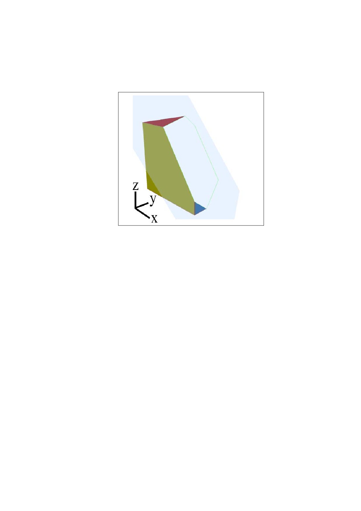
Figure 77 shows the cross section specified for the 3DView that references CrossSection3. This cross section
specifies a plane that differs from the one specified in CrossSection1 (Figure 75) in the following way:
•
Perpendicular to the X axis, parallel to the Y axis, and rotated 30 degrees around the Z axis: /O [ null 0 30]
Figure 78 - Rendering of the 3D artwork using View4
(cross section rotated around the y axis by -30 degrees and around the z axis by 30 degrees)
Figure 78 shows the cross section specified for the 3DView that references CrossSection4. This cross section
specifies a plane that differs from the one specified in CrossSection1 (Figure 75) in the following way:
•
Perpendicular to the X axis, rotated -30 degrees around the Y axis, and rotated 30 degrees around the Z
axis: /O [ null -30 30]
13.6.4.7
3D Node Dictionaries
A 3D view may specify a 3D node dictionary (PDF 1.7), which specifies particular areas of 3D artwork and the
opacity and visibility with which individual nodes shall be displayed. The 3D artwork shall be contained in the
parent 3D stream object. The NA entry of the 3D views dictionary may specify multiple 3D node dictionaries for
a particular view.
NOTE 1
While many PDF dictionaries reference 3D artwork in its entirety, it is often useful to reference 3D artwork at a
more granular level. This enables properties such as visibility, opacity, and orientation to be applied to subsets
of the 3D artwork. These controls enable underlying nodes to be revealed, by making the overlying nodes
transparent or by moving them out of the way.
NOTE 2
Do not confuse nodes with view nodes. A node is a PDF dictionary that specifies an area in 3D artwork, while
a view node is a parameter in the 3D artwork that specifies a view.
Table 312 shows the entries in a 3D node dictionary.
537

Table 312 - Entries in a 3D node dictionary
Key
Type
Value
Type
name
(Optional) The type of PDF object that this dictionary
describes; if present, shall be
3DNode for a 3D node
dictionary.
N
text string
(Required) The name of the node being described by the
node dictionary. If the Subtype of the corresponding 3D
Stream is U3D, this entry corresponds to the field Node block
name, as described in the Universal
3D file format
specification (see Bibliography). In the future, nodes may be
described using other 3D conventions.
NOTE
When comparing this entry to node names for a
particular convention
(such as Universal 3D),
conforming readers shall translate between the
PDF text encoding used by PDF and the
character encoding specified in the 3D stream.
O
number
(Optional) A number in the range [0, 1] indicating the opacity
of the geometry supplied by this node using a standard
additive blend mode.
If this entry is absent, the viewer shall use the opacity
specified for the parent node or for the
3D artwork (in
ascending order).
V
boolean
(Optional) A flag indicating the visibility of this node. If true,
then the node is visible. If false, then the node shall not be
visible.
If this entry shall be absent, the viewer shall use the visibility
specified for the parent node or for the
3D artwork (in
ascending order).
M
array
(Optional) A
12-element
3D transformation matrix that
specifies the position and orientation of this node, relative to
its parent, in world coordinates
(see
13.6.5,
“Coordinate
Systems for 3D”).
The N entry specifies which node in the 3D stream corresponds to this node dictionary.
The O entry describes the opacity that shall be used when rendering this node, and the V entry shall determine
whether or not the node is rendered at all. While a node with an opacity of 0 shall be rendered in the same way
as a non-visible node, having a separate value for the visibility of a node allows interactive conforming readers
to show/hide partially transparent nodes, without overwriting the intended opacity of those nodes.
The M entry specifies the node’s matrix relative to its parent, in world coordinates. If an hierarchy of nodes is
intended to be repositioned while still maintaining its internal structure, then only the node at the root of the
hierarchy needs to be adjusted.
EXAMPLE
The following example shows a 3D view specifying an array of node parameters.
3 0 obj
% Default node params with all shapes visible and opaque
[
<< /Type /3DNode
/N (Sphere)
/O 1
/V true
/M [...]>>
<< /Type /3DNode
/N (Cone)
/O 1
/V true >>
538
<< /Type /3DNode
/N (Cube)
/O 1
/V true >>
]
4 0 obj
% Params with the cone hidden and the sphere semi-transparent
[
<< /Type /3DNode
/N (Sphere)
/O 0.5
/V true >>
<< /Type /3DNode
/N (Cone)
/O 1
/V false >>
<< /Type /3DNode
/N (Cube)
/O 1
/V true >>
]
endobj
5 0 obj
%View1, using the default set of node params
<<
/Type /3DView
/XN (View1)
/NA 3 0 R
>>
endobj
6 0 obj
%View2, using the alternate set of node params
<<
/Type /3DView
/XN (View2)
/NA 4 0 R
>>
endobj
539
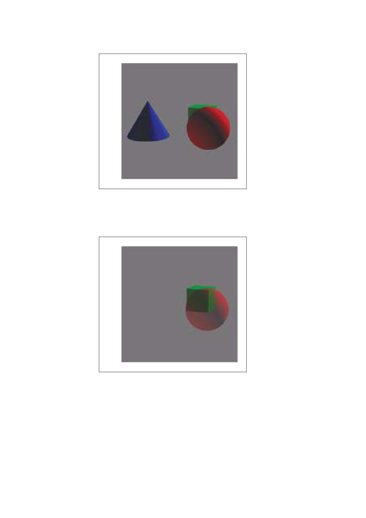
Figure 79 - Rendering of the 3D artwork using View1 (all shapes visible and opaque)
Figure 79 shows a view whose node array includes three nodes, all of which shall be rendered with the
appearance opaque (/O 1) and visible (/V true).
Figure 80 - Rendering of the 3D artwork using View2 (the cone is hidden and the sphere is semi-
transparent)
Figure 80 shows a view with a node array that specifies the same three nodes used in Figure 79. These nodes
have the following display characteristics:
•
The node named Sphere is partially transparent (/O 0.5) and visible (/V true)
•
The node named Cone is opaque (/O 1) and invisible (/V false)
•
The node named Cube is opaque (/O 1) and visible (/V true)
540
13.6.5
Coordinate Systems for 3D
3D artwork is a collection of objects whose positions and geometry shall be specified using three-dimensional
coordinates. 8.3, “Coordinate Systems,” discusses the concepts of two-dimensional coordinate systems, their
geometry and transformations. This sub-clause extends those concepts to include the third dimension.
As described in 8.3, “Coordinate Systems,” positions shall be defined in terms of pairs of x and y coordinates
on the Cartesian plane. The origin of the plane specifies the location (0, 0); x values increase to the right and y
values increase upward. For three-dimensional graphics, a third axis, the z axis, shall be used. The origin shall
be at (0, 0, 0); positive z values increase going into the page.
In two-dimensional graphics, the transformation matrix transforms the position, size, and orientation of objects
in a plane. It is a 3-by-3 matrix, where only six of the elements may be changed; therefore, the matrix shall be
expressed in PDF as an array of six numbers:
a b 0
c d 0
=
a b c d tx ty
tx ty 1
In 3D graphics, a 4-by-4 matrix shall be used to transform the position, size, and orientations of objects in a
three-dimensional coordinate system. Only the first three columns of the matrix may be changed; therefore, the
matrix shall be expressed in PDF as an array of 12 numbers:
a b c
0
d e f
0
=
a b c d e f g h i tx ty tz
g h i
0
tx ty tz 1
3D coordinate transformations shall be expressed as matrix transformations:
a b c 0
d e f
0
=
×
x' y' z' 1
x y z 1
g h i
0
tx ty tz 1
Carrying out the multiplication has the following results:
x'
= a×x+d×y+g×z+tx
y'
= b×x+e×y+h×z+ty
z'
= c×x+f×y+i×z+tz
Position and orientation of 3D artwork typically involves translation (movement) and rotation along any axis.
The virtual camera represents the view of the artwork. The relationship between camera and artwork may be
thought of in two ways:
•
The 3D artwork is in a fixed position and orientation, and the camera moves to different positions and
orientations.
•
The camera is in a fixed location, and the 3D artwork is translated and rotated.
541
Both approaches may achieve the same visual effects; in practice, 3D systems typically use a combination of
both. Conceptually, there are three distinct coordinate systems:
•
The artwork coordinate system.
•
The camera coordinate system, in which the camera shall be positioned at (0, 0, 0) facing out along the
positive z axis, with the positive x axis to the right and the positive y axis going straight up.
•
An intermediate system called the world coordinate system.
Two 3D transformation matrices shall be used in coordinate conversions:
•
The artwork-to-world matrix specifies the position and orientation of the artwork in the world coordinate
system. This matrix shall be contained in the 3D stream.
•
The camera-to-world matrix specifies the position and orientation of the camera in the world coordinate
system. This matrix shall be specified by either the C2W or U3DPath entries of the 3D view dictionary.
When drawing 3D artwork in a 3D annotation’s target coordinate system, the following transformations take
place:
a) Artwork coordinates shall be transformed to world coordinates:
xw yw zw 1
=
xa ya za
1
×aw
b) World coordinates shall be transformed to camera coordinates:
–
xc yc zc 1
=
xw yw zw 1
×(c
)
c) The first two steps can be expressed as a single equation, as follows:
–
xc yc zc 1
=
xa ya za 1
×
(aw×c
)
d) Finally, the camera coordinates shall be projected into two dimensions, eliminating the z coordinate, then
scaled and positioned within the annotation’s target coordinate system.
13.6.6
3D Markup
Beginning with PDF 1.7, users may comment on specific views of 3D artwork by using markup annotations
(see 12.5.6.2, “Markup Annotations”). Markup annotations (as other annotations) are normally associated with
a location on a page. To associate the markup with a specific view of a 3D annotation, the annotation dictionary
for the markup annotation contains an ExData entry (see Table 174) that specifies the 3D annotation and view.
Table 313 describes the entries in an external data dictionary used to markup 3D annotations.
542

Table 313 - Entries in an external data dictionary used to markup 3D annotations
Key
Type
Value
Type
name
(Required) The type of PDF object that this dictionary describes; if present,
shall be ExData for an external data dictionary.
Subtype
name
(Required) The type of external data that this dictionary describes; shall be
Markup3D for a 3D comment. The only defined value is Markup3D.
3DA
dictionary or
(Required) The 3D annotation to which this markup annotation applies. The
text string
3D annotation may be specified as a child dictionary or as the name of a 3D
annotation, as specified by its NM entry. In the latter case, the 3D annotation
and the markup annotation shall be on the same page of the document.
3DV
dictionary
(Required) The 3D view that this markup annotation is associated with. The
annotation will be hidden unless this view is currently being used for the 3D
annotation specified by 3DA.
MD5
byte string
(Optional) A 16-byte string that contains the checksum of the bytes of the 3D
stream data that this 3D comment shall be associated with. The checksum
shall be calculated by applying the standard MD5 message-digest algorithm
(described in Internet RFC 1321, The MD5 Message-Digest Algorithm; see
the Bibliography) to the bytes of the stream data. This value shall be used to
determine if artwork data has changed since this 3D comment was created.
In a Markup3D ExData dictionary, the 3DA entry identifies the 3D annotation to which the markup shall be
associated. Even though the markup annotation exists alongside the associated annotation in the page’s
Annots array, the markup may be thought of as a child of the 3DA annotation.
The 3DV entry specifies the markup’s associated 3D view. The markup shall only be printed and displayed
when the specified view is the current view of its parent 3D annotation. This ensures that the proper context is
preserved when the markup is displayed.
NOTE
An equivalent view is not sufficient; if more than one markup specify equivalent views represented by different
objects, the markups will not display simultaneously.
The MD5 entry gives conforming readers a means to detect whether or not the 3D stream of the 3D annotation
specified by 3DA has changed. If the 3D stream has changed, the context provided by the 3DV entry may no
longer apply, and the markup may no longer be useful. Any action taken as a response to such a situation is
dependent on the conforming reader, but a warning shall be issued to the user.
EXAMPLE
The following example shows how markup annotations can be associated with particular views.
2 0 obj
% 3D stream data with two named views
<<
/Type /3D
/Subtype /U3D
/VA [4 0 R 5 0 R]
>>
stream
endstream
endobj
3 0 obj
% 3D annotation
<<
/Type /Annot
/Subtype /3D
/3DD 2 0 R
543
>>
endobj
4 0 obj
% CommentView1
<<
/Type /3DView
/XN (CommentView1)
>>
endobj
5 0 obj
% CommentView2
<<
/Type /3DView
/XN (CommentView2)
>>
endobj
6 0 obj
% Cloud comment with no ExData
<<
/Type /Annot
/Subtype /Polygon
/IT /PolygonCloud
>>
endobj
7 0 obj
% Callout comment on CommentView1
<<
/Type /Annot
/Subtype /FreeText
/IT /FreeTextCallout
/ExData <<
/Type /Markup3D
/3DA 3 0 R
/3DV 4 0 R
>>
>>
endobj
8 0 obj
% Dimension comment on CommentView2
<<
/Type /Annot
/Subtype /Line
/IT /LineDimension
/ExData <<
/Type /Markup3D
/3DA 3 0 R
/3DV 5 0 R
>>
>>
544
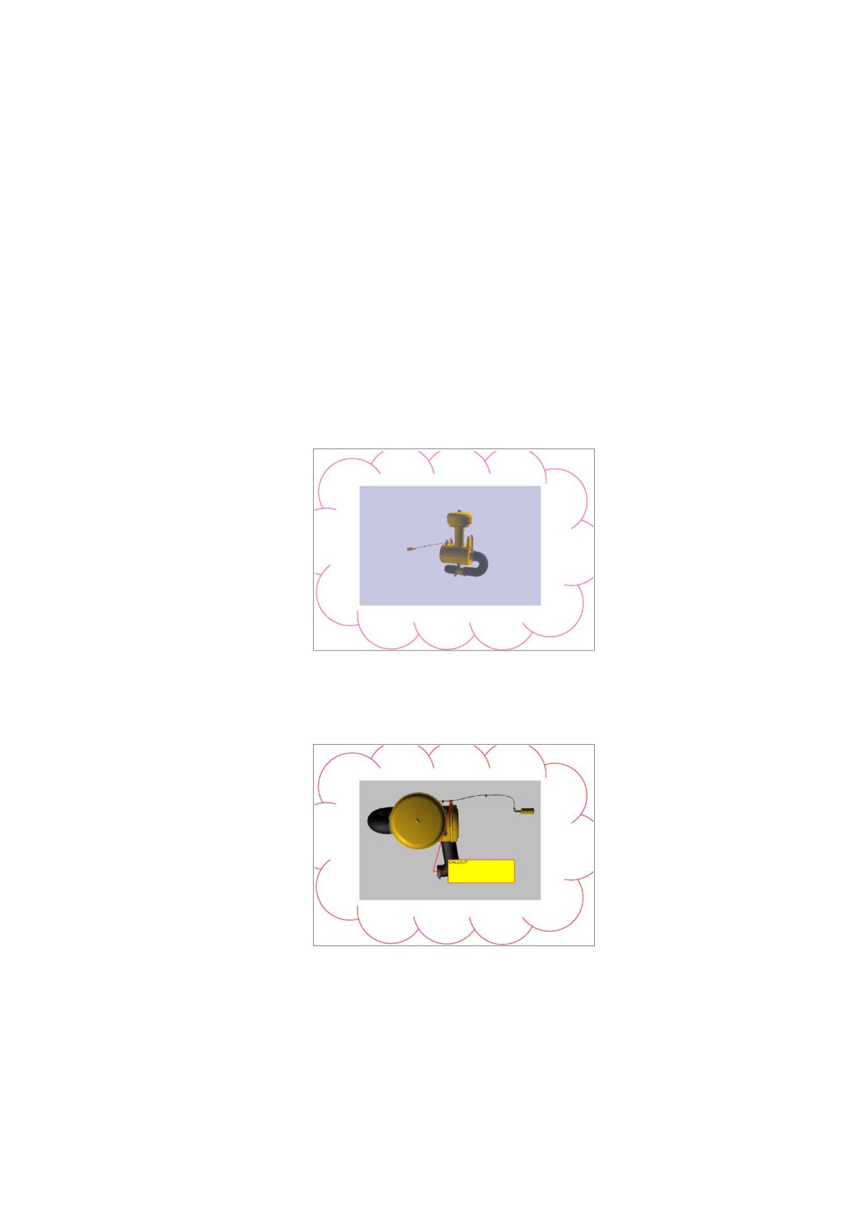
endobj
9 0 obj
% Stamp comment on CommentView2
<<
/Type /Annot
/Subtype /Stamp
/ExData <<
/Type /Markup3D
/3DA 3 0 R
/3DV 5 0 R
>>
>>
endobj
The following illustrations show the placement of markup on annotations on different views of the same 3D
artwork.
Figure 81 - 3D artwork set to its default view
Figure 81 shows the default view, which has no markup annotations.
Figure 82 - 3D artwork set to CommentView1
Figure 82 shows another view to which a markup annotation is applied.
545
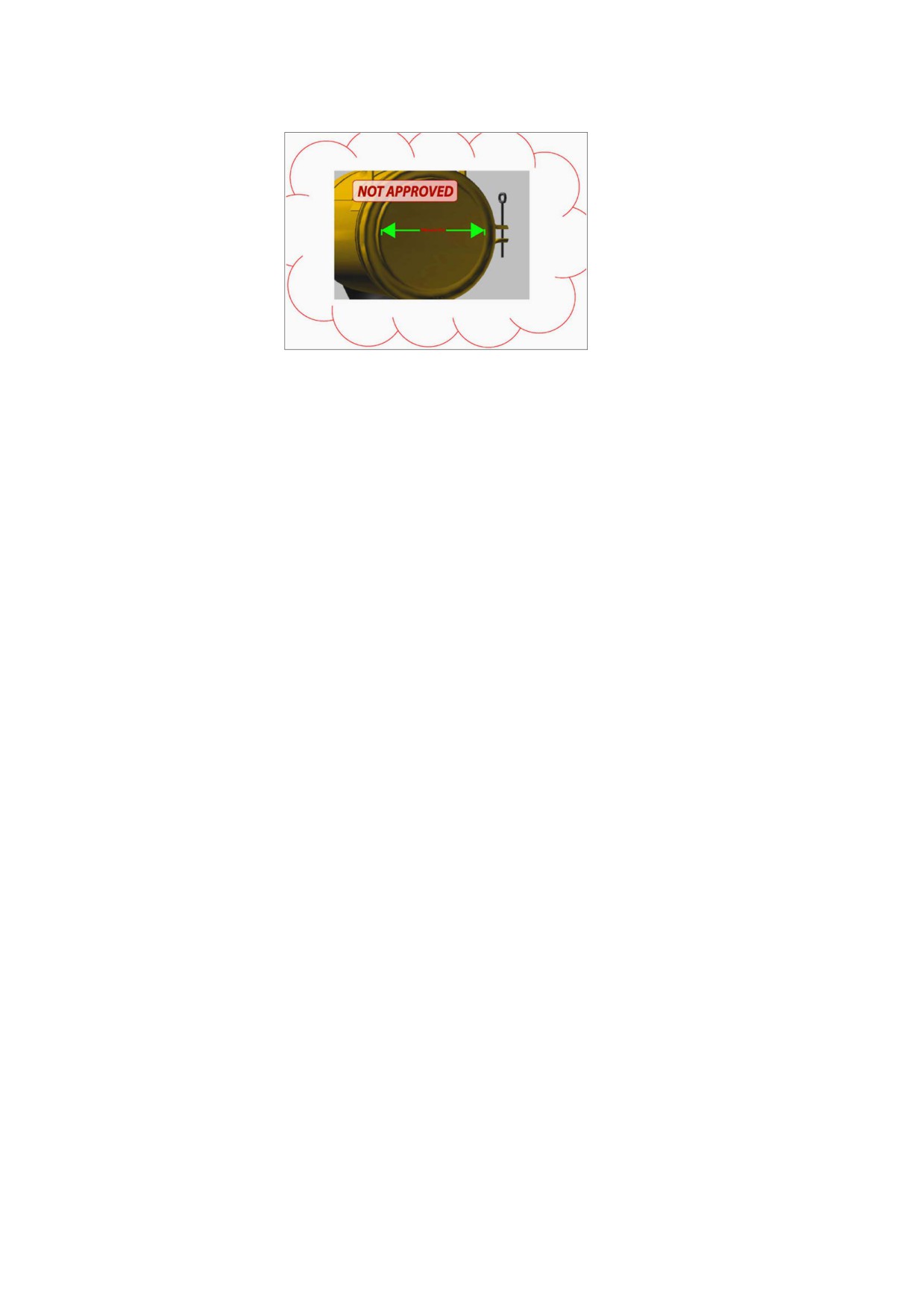
Figure 83 - 3D artwork set to CommentView2
Figure 83 shows a view referenced by two markup annotations:
•
A line annotation (/Subtype /Line) with a line dimension intent
(/IT/ LineDimension)
•
A stamp annotation (/Subtype /Stamp)
546

14
Document Interchange
14.1
General
The features described in this clause do not affect the final appearance of a document. Rather, these features
enable a document to include higher-level information that is useful for the interchange of documents among
conforming products:
•
Procedure sets (14.2, “Procedure Sets”) that define the implementation of PDF operators
•
Metadata (14.3, “Metadata”) consisting of general information about a document or a component of a
document, such as its title, author, and creation and modification dates
•
File identifiers (14.4, “File Identifiers”) for reliable reference from one PDF file to another
•
Page-piece dictionaries (14.5, “Page-Piece Dictionaries”) allowing a conforming product to embed private
data in a PDF document for its own use
•
Marked-content operators (14.6, “Marked Content”) for identifying portions of a content stream and
associating them with additional properties or externally specified objects
•
Logical structure facilities (14.7, “Logical Structure”) for imposing a hierarchical organization on the content
of a document
•
Tagged PDF (14.8, “Tagged PDF”), a set of conventions for using the marked content and logical structure
facilities to facilitate the extraction and reuse of a document’s content for other purposes
•
Various ways of increasing the accessibility of a document to users with disabilities (14.9, “Accessibility
Support”), including the identification of the natural language in which it is written (such as English or
Spanish) for the benefit of a text-to-speech engine
•
The Web Capture extension (14.10, “ Web Capture”), which creates PDF files from Internet-based or
locally resident HTML, PDF, GIF, JPEG, and ASCII text files
•
Facilities supporting prepress production workflows (14.11, “Prepress Support”), such as the specification
of page boundaries and the generation of printer’s marks, colour separations, output intents, traps, and
low-resolution proxies for high-resolution images
14.2
Procedure Sets
The PDF operators used in content streams are grouped into categories of related operators called procedure
sets (see Table 314). Each procedure set corresponds to a named resource containing the implementations of
the operators in that procedure set. The ProcSet entry in a content stream’s resource dictionary (see 7.8.3,
“Resource Dictionaries”) shall hold an array consisting of the names of the procedure sets used in that content
stream. These procedure sets shall be used only when the content stream is printed to a PostScript output
device. The names identify PostScript procedure sets that shall be sent to the device to interpret the PDF
operators in the content stream. Each element of this array shall be one of the predefined names shown in
Table 314.
Table 314 - Predefined procedure set
Name
Category of operators
PDF
Painting and graphics state
Text
Text
ImageB
Grayscale images or image masks
547

Table 314 - Predefined procedure set (continued)
Name
Category of operators
ImageC
Colour images
ImageI
Indexed (colour-table) images
Beginning with PDF 1.4, this feature is considered obsolete. For compatibility with existing conforming readers,
conforming writers should continue to specify procedure sets (preferably, all of those listed in Table 314 unless
it is known that fewer are needed). However, conforming readers should not depend on the correctness of this
information.
14.3
Metadata
14.3.1
General
A PDF document may include general information, such as the document’s title, author, and creation and
modification dates. Such global information about the document (as opposed to its content or structure) is
called metadata and is intended to assist in cataloguing and searching for documents in external databases.
Beginning with PDF 1.4, metadata may also be specified for individual components of a document.
Metadata may be stored in a PDF document in either of the following ways:
•
In a metadata stream (PDF 1.4) associated with the document or a component of the document (14.3.2,
“Metadata Streams”)
•
In a document information dictionary associated with the document (14.3.3, “Document Information
Dictionary”)
NOTE
Document information dictionaries is the original way that metadata was included in a PDF file. Metadata
streams were introduced in PDF 1.4 and is now the preferred method to include metadata.
14.3.2
Metadata Streams
Metadata, both for an entire document and for components within a document, may be stored in PDF streams
called metadata streams (PDF 1.4).
NOTE 1
Metadata streams have the following advantages over the document information dictionary:
•
PDF-based workflows often embed metadata-bearing artwork as components within larger documents.
Metadata streams provide a standard way of preserving the metadata of these components for
examination downstream. PDF-aware conforming products should be able to derive a list of all metadata-
bearing document components from the PDF document itself.
•
PDF documents are often made available on the Web or in other environments, where many tools routinely
examine, catalogue, and classify documents. These tools should be able to understand the self-contained
description of the document even if they do not understand PDF.
Besides the usual entries common to all stream dictionaries (see Table 5), the metadata stream dictionary shall
contain the additional entries listed in Table 315.
The contents of a metadata stream shall be the metadata represented in Extensible Markup Language (XML).
NOTE 2
This information is visible as plain text to tools that are not PDF-aware only if the metadata stream is both
unfiltered and unencrypted.
548
Table 315 - Additional entries in a metadata stream dictionary
Key
Type
Value
Type
name
(Required) The type of PDF object that this dictionary describes; shall be
Metadata for a metadata stream.
Subtype
name
(Required) The type of metadata stream that this dictionary describes; shall
be XML.
NOTE 3
The format of the XML representing the metadata is defined as part of a framework called the Extensible
Metadata Platform (XMP) and described in the Adobe document XMP: Extensible Metadata Platform (see the
Bibliography). This framework provides a way to use XML to represent metadata describing documents and
their components and is intended to be adopted by a wider class of products than just those that process PDF.
It includes a method to embed XML data within non-XML data files in a platform-independent format that can
be easily located and accessed by simple scanning rather than requiring the document file to be parsed.
A metadata stream may be attached to a document through the Metadata entry in the document catalogue
(see 7.7.2, “Document Catalog”). The metadata framework provides a date stamp for metadata expressed in
the framework. If this date stamp is equal to or later than the document modification date recorded in the
document information dictionary, the metadata stream shall be taken as authoritative. If, however, the
document modification date recorded in the document information dictionary is later than the metadata
stream’s date stamp, the document has likely been saved by a writer that is not aware of metadata streams. In
this case, information stored in the document information dictionary shall be taken to override any semantically
equivalent items in the metadata stream. In addition, PDF document components represented as a stream or
dictionary may have a Metadata entry (see Table 316).
Table 316 - Additional entry for components having metadata
Key
Type
Value
Metadata
stream
(Optional; PDF 1.4) A metadata stream containing metadata for the
component.
In general, any PDF stream or dictionary may have metadata attached to it as long as the stream or dictionary
represents an actual information resource, as opposed to serving as an implementation artifact. Some PDF
constructs are considered implementational, and hence may not have associated metadata.
When there is ambiguity about exactly which stream or dictionary may bear the Metadata entry, the metadata
shall be attached as close as possible to the object that actually stores the data resource described.
NOTE 4
Metadata describing a tiling pattern should be attached to the pattern stream’s dictionary, but a shading should
have metadata attached to the shading dictionary rather than to the shading pattern dictionary that refers to it.
Similarly, metadata describing an ICCBased colour space should be attached to the ICC profile stream
describing it, and metadata for fonts should be attached to font file streams rather than to font dictionaries.
NOTE 5
In tables describing document components in this specification, the Metadata entry is listed only for those in
which it is most likely to be used. Keep in mind, however, that this entry may appear in other components
represented as streams or dictionaries.
•
In addition, metadata may also be associated with marked content within a content stream. This
association shall be created by including an entry in the property list dictionary whose key shall be
Metadata and whose value shall be the metadata stream dictionary. Because this construct refers to an
object outside the content stream, the property list is referred to indirectly as a named resource (see
14.6.2, “Property Lists”).
14.3.3
Document Information Dictionary
The optional Info entry in the trailer of a PDF file (see 7.5.5, “File Trailer”) shall hold a document information
dictionary containing metadata for the document; Table 317 shows its contents. Any entry whose value is not
known should be omitted from the dictionary rather than included with an empty string as its value.
549

Some conforming readers may choose to permit searches on the contents of the document information
dictionary. To facilitate browsing and editing, all keys in the dictionary shall be fully spelled out, not abbreviated.
New keys should be chosen with care so that they make sense to users.
The value associated with any key not specifically mentioned in Table 317 shall be a text string.
Although conforming readers may store custom metadata in the document information dictionary, they may not
store private content or structural information there. Such information shall be stored in the document
catalogue instead (see 7.7.2, “Document Catalog”).
Table 317 - Entries in the document information dictionary
Key
Type
Value
Title
text string
(Optional; PDF 1.1) The document’s title.
Author
text string
(Optional) The name of the person who created the document.
Subject
text string
(Optional; PDF 1.1) The subject of the document.
Keywords
text string
(Optional; PDF 1.1) Keywords associated with the document.
Creator
text string
(Optional) If the document was converted to PDF from another format,
the name of the conforming product that created the original document
from which it was converted.
Producer
text string
(Optional) If the document was converted to PDF from another format,
the name of the conforming product that converted it to PDF.
CreationDate
date
(Optional) The date and time the document was created, in human-
readable form (see 7.9.4, “Dates”).
ModDate
date
(Required if PieceInfo is present in the document catalogue;
otherwise optional; PDF 1.1) The date and time the document was
most recently modified, in human-readable form (see 7.9.4, “Dates”).
Trapped
name
(Optional; PDF 1.3) A name object indicating whether the document
has been modified to include trapping information
(see
14.11.6,
“Trapping Support”):
True
The document has been fully trapped; no further trapping
shall be needed. This shall be the name True, not the
boolean value true.
False
The document has not yet been trapped. This shall be the
name False, not the boolean value false.
Unknown Either it is unknown whether the document has been
trapped or it has been partly but not yet fully trapped; some
additional trapping may still be needed.
Default value: Unknown.
NOTE
The value of this entry may be set automatically by the
software creating the document’s trapping information, or
it may be known only to a human operator and entered
manually.
EXAMPLE
This example shows a typical document information dictionary.
1 0 obj
<<
/Title
( PostScript Language Reference, Third Edition )
/Author ( Adobe Systems Incorporated )
/Creator ( Adobe FrameMaker 5 . 5 . 3 for Power Macintosh® )
/Producer ( Acrobat Distiller 3 . 01 for Power Macintosh )
/CreationDate ( D : 19970915110347 - 08' 00' )
/ModDate ( D : 19990209153925 - 08' 00' )
>>
endobj
550
14.4
File Identifiers
PDF files may contain references to other PDF files (see 7.11, “File Specifications”). Simply storing a file name,
however, even in a platform-independent format, does not guarantee that the file can be found. Even if the file
still exists and its name has not been changed, different server software applications may identify it in different
ways. Servers running on DOS platforms convert all file names to 8 characters and a 3-character extension.
Different servers may use different strategies for converting longer file names to this format.
External file references may be made more reliable by including a file identifier (PDF 1.1) in the file and using it
in addition to the normal platform-based file designation. Matching the identifier in the file reference with the
one in the file confirms whether the correct file was found.
File identifiers shall be defined by the optional ID entry in a PDF file’s trailer dictionary (see 7.5.5, “File Trailer”).
The ID entry is optional but should be used. The value of this entry shall be an array of two byte strings. The
first byte string shall be a permanent identifier based on the contents of the file at the time it was originally
created and shall not change when the file is incrementally updated. The second byte string shall be a
changing identifier based on the file’s contents at the time it was last updated. When a file is first written, both
identifiers shall be set to the same value. If both identifiers match when a file reference is resolved, it is very
likely that the correct and unchanged file has been found. If only the first identifier matches, a different version
of the correct file has been found.
To help ensure the uniqueness of file identifiers, they should be computed by means of a message digest
algorithm such as MD5 (described in Internet RFC 1321, The MD5 Message-Digest Algorithm; see the
Bibliography), using the following information:
•
The current time
•
A string representation of the file’s location, usually a pathname
•
The size of the file in bytes
•
The values of all entries in the file’s document information dictionary (see 14.3.3, “Document Information
Dictionary”)
NOTE
The calculation of the file identifier need not be reproducible; all that matters is that the identifier is likely to be
unique. For example, two implementations of the preceding algorithm might use different formats for the
current time, causing them to produce different file identifiers for the same file created at the same time, but the
uniqueness of the identifier is not affected.
14.5
Page-Piece Dictionaries
A page-piece dictionary (PDF 1.3) may be used to hold private conforming product data. The data may be
associated with a page or form XObject by means of the optional PieceInfo entry in the page object (see
Table 30) or form dictionary (see Table 95). Beginning with PDF 1.4, private data may also be associated with
the PDF document by means of the PieceInfo entry in the document catalogue (see Table 28).
NOTE 1
Conforming products may use this dictionary as a place to store private data in connection with that document,
page, or form. Such private data can convey information meaningful to the conforming product that produces it
(such as information on object grouping for a graphics editor or the layer information used by Adobe
Photoshop®) but may be ignored by general-purpose conforming readers.
As Table 318 shows, a page-piece dictionary may contain any number of entries, each keyed by the name of a
distinct conforming product or of a well-known data type recognized by a family of conforming products. The
value associated with each key shall be a data dictionary containing the private data that shall be used by the
conforming product. The Private entry may have a value of any data type, but typically it is a dictionary
containing all of the private data needed by the conforming product other than the actual content of the
document, page, or form.
551

Table 318 - Entries in a page-piece dictionary
Key
Type
Value
any conforming
dictionary
A data dictionary (see Table 319).
product name or well-
known data type
Table 319 - Entries in an data dictionary
Key
Type
Value
LastModified
date
(Required) The date and time when the contents of the
document, page, or form were most recently modified by this
conforming product.
Private
(any)
(Optional) Any private data appropriate to the conforming
product, typically in the form of a dictionary.
The LastModified entry indicates when this conforming product last altered the content of the page or form. If
the page-piece dictionary contains several data dictionaries, their modification dates can be compared with
those in the corresponding entry of the page object or form dictionary (see Table 30 and Table 95), or the
ModDate entry of the document information dictionary (see Table 317), to ascertain which data dictionary
corresponds to the current content of the page or form. Because some platforms may use only an approximate
value for the date and time or may not deal correctly with differing time zones, modification dates shall be
compared only for equality and not for sequential ordering.
NOTE 2
It is possible for two or more data dictionaries to have the same modification date. Conforming products can
use this capability to define multiple or extended versions of the same data format. For example, suppose that
earlier versions of a conforming product use an data dictionary named PictureEdit, and later versions of the
same conforming product extend the data to include additional items not previously used. The original data
could continue to be kept in the PictureEdit dictionary and the additional items placed in a new dictionary
named PictureEditExtended. This allows the earlier versions of the conforming product to continue to work as
before, and later versions are able to locate and use the extended data items.
14.6
Marked Content
14.6.1
General
Marked-content operators (PDF 1.2) may identify a portion of a PDF content stream as a marked-content
element of interest to a particular conforming product. Marked-content elements and the operators that mark
them shall fall into two categories:
•
The MP and DP operators shall designate a single marked-content point in the content stream.
•
The BMC, BDC, and EMC operators shall bracket a marked-content sequence of objects within the
content stream.
NOTE 1
This is a sequence not simply of bytes in the content stream but of complete graphics objects. Each object is
fully qualified by the parameters of the graphics state in which it is rendered.
NOTE 2
A graphics application, for example, might use marked content to identify a set of related objects as a group to
be processed as a single unit. A text-processing application might use it to maintain a connection between a
footnote marker in the body of a document and the corresponding footnote text at the bottom of the page. The
PDF logical structure facilities use marked-content sequences to associate graphical content with structure
elements (see 14.7.4, “Structure Content”). Table 320 summarizes the marked-content operators.
All marked-content operators except EMC shall take a tag operand indicating the role or significance of the
marked-content element to the conforming reader. All such tags shall be registered with Adobe Systems (see
552