ISO 32000-1 Document management — Portable document format — Part 1: PDF 1.7 - page 5
dictionary. Regardless of how the colour space is specified, it shall be subject to remapping as described
below.
When a device colour space is selected, the ColorSpace subdictionary of the current resource dictionary (see
7.8.3, "Resource Dictionaries") is checked for the presence of an entry designating a corresponding default
colour space (DefaultGray, DefaultRGB, or DefaultCMYK, corresponding to DeviceGray, DeviceRGB, or
DeviceCMYK, respectively). If such an entry is present, its value shall be used as the colour space for the
operation currently being performed.
Colour values in the original device colour space shall be passed unchanged to the default colour space, which
shall have the same number of components as the original space. The default colour space should be chosen
to be compatible with the original, taking into account the components’ ranges and whether the components
are additive or subtractive. If a colour value lies outside the range of the default colour space, it shall be
adjusted to the nearest valid value.
Any colour space other than a Lab, Indexed, or Pattern colour space may be used as a default colour space
and it should be compatible with the original device colour space as described above.
If the selected space is a special colour space based on an underlying device colour space, the default colour
space shall be used in place of the underlying space. This shall apply to the following colour spaces:
•
The underlying colour space of a Pattern colour space
•
The base colour space of an Indexed colour space
•
The alternate colour space of a Separation or DeviceN colour space (but only if the alternate colour space
is actually selected)
See 8.6.6, "Special Colour Spaces", for details on these colour spaces.
There is no conversion of colour values, such as a tint transformation, when using the default colour space.
Colour values that are within the range of the device colour space might not be within the range of the default
colour space (particularly if the default is an ICCBased colour space). In this case, the nearest values within
the range of the default space are used. For this reason, a Lab colour space shall not be used as the
DefaultRGB colour space.
8.6.5.7
Implicit Conversion of CIE-Based Colour Spaces
In cases where a source colour space accurately represents the particular output device being used, a
conforming reader should avoid converting the component colour values but use the source values directly as
output values. This avoids any unwanted computational error and in the case of 4 component colour spaces
avoids the conversion from 4 components to 3 and back to 4, a process that loses critical colour information.
NOTE 1
In workflows in which PDF documents are intended for rendering on a specific target output device (such as a
printing press with particular inks and media), it is often useful to specify the source colours for some or all of a
document’s objects in a CIE-based colour space that matches the calibration of the intended device. The
resulting document, although tailored to the specific characteristics of the target device, remains device-
independent and will produce reasonable results if retargeted to a different output device. However, the
expectation is that if the document is printed on the intended target device, source colours that have been
specified in a colour space matching the calibration of the device will pass through unchanged, without
conversion to and from the intermediate CIE 1931 XYZ space as depicted in Figure 22.
NOTE 2
In particular, when colours intended for a CMYK output device are specified in an ICCBased colour space
using a matching CMYK printing profile, converting such colours from four components to three and back is
unnecessary and results in a loss of fidelity in the black component. In such cases, a conforming reader may
provide the ability for the user to specify a particular calibration to use for printing, proofing, or previewing. This
calibration is then considered to be that of the native colour space of the intended output device (typically
DeviceCMYK), and colours expressed in a CIE-based source colour space matching it can be treated as if
they were specified directly in the device’s native colour space.
153
NOTE 3
The conditions under which such implicit conversion is done cannot be specified in PDF, since nothing in PDF
describes the calibration of the output device (although an output intent dictionary, if present, may suggest
such a calibration; see 14.11.5, "Output Intents"). The conversion is completely hidden by the conforming
reader and plays no part in the interpretation of PDF colour spaces.
When this type of implicit conversion is done, all of the semantics of the device colour space shall also apply,
even though they do not apply to CIE-based spaces in general. In particular:
•
The nonzero overprint mode (see 8.6.7, "Overprint Control") shall determine the interpretation of colour
component values in the space.
•
If the space is used as the blending colour space for a transparency group in the transparent imaging
model (see 11.3.4, "Blending Colour Space"; 11.4, "Transparency Groups"; and 11.6.6, "Transparency
Group XObjects"), components of the space, such as Cyan, may be selected in a Separation or DeviceN
colour space used within the group (see 8.6.6.4, "Separation Colour Spaces" and 8.6.6.5, "DeviceN Colour
Spaces").
•
Likewise, any uses of device colour spaces for objects within such a transparency group have well-defined
conversions to the group colour space.
NOTE 4
A source colour space can be specified directly (for example, with an ICCBased colour space) or indirectly
using the default colour space mechanism (for example, DefaultCMYK; see 8.6.5.6, "Default Colour Spaces").
The implicit conversion of a CIE-based colour space to a device space should not depend on whether the CIE-
based space is specified directly or indirectly.
8.6.5.8
Rendering Intents
Although CIE-based colour specifications are theoretically device-independent, they are subject to practical
limitations in the colour reproduction capabilities of the output device. Such limitations may sometimes require
compromises to be made among various properties of a colour specification when rendering colours for a given
device. Specifying a rendering intent (PDF 1.1) allows a conforming writer to set priorities regarding which of
these properties to preserve and which to sacrifice.
EXAMPLE
The conforming writer might request that colours falling within the output device’s gamut (the range of
colours it can reproduce) be rendered exactly while sacrificing the accuracy of out-of-gamut colours, or
that a scanned image such as a photograph be rendered in a perceptually pleasing manner at the cost of
strict colourimetric accuracy.
Rendering intents shall be specified with the ri operator (see 8.4.4, "Graphics State Operators"), the RI entry in
a graphics state parameter dictionary (see 8.4.5, "Graphics State Parameter Dictionaries"), or with the Intent
entry in image dictionaries (see 8.9.5, "Image Dictionaries"). The value shall be a name identifying the
rendering intent. Table 70 lists the standard rendering intents that shall be recognized. Figure L.5 in Annex L
illustrates their effects. These intents have been chosen to correspond to those defined by the International
Color Consortium (ICC), an industry organization that has developed standards for device-independent colour.
If a conforming reader does not recognize the specified name, it shall use the RelativeColorimetric intent by
default.
NOTE
Note, however, that the exact set of rendering intents supported may vary from one output device to another; a
particular device may not support all possible intents or may support additional ones beyond those listed in the
table.
See 11.7.5, "Rendering Parameters and Transparency", and in particular 11.7.5.3, "Rendering Intent and
Colour Conversions", for further discussion of the role of rendering intents in the transparent imaging model.
154
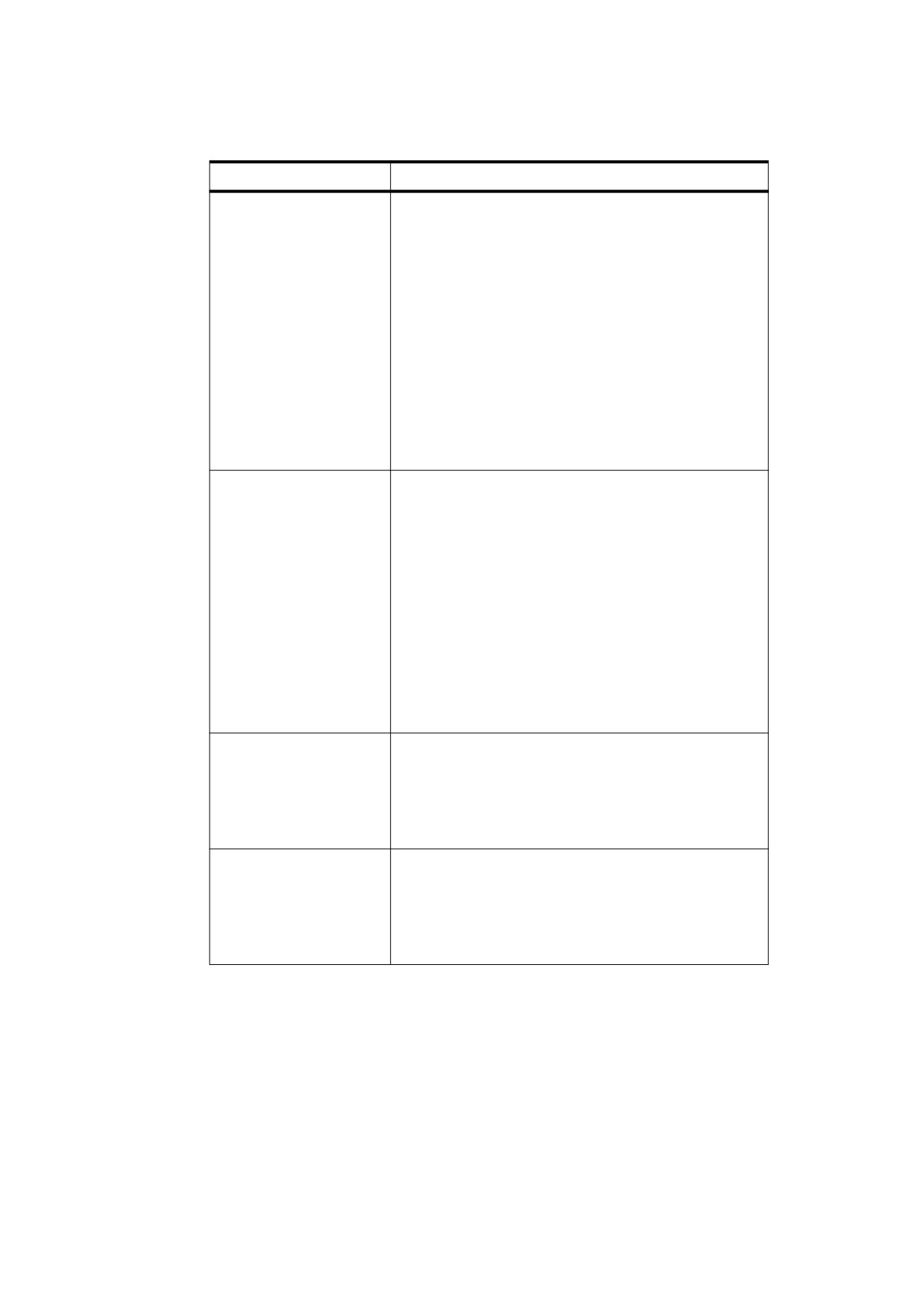
Table 70 - Rendering Intents
Name
Description
AbsoluteColorimetric
Colours shall be represented solely with respect to the
light source; no correction shall be made for the output
medium’s white point (such as the colour of unprinted
paper). Thus, for example, a monitor’s white point, which
is bluish compared to that of a printer’s paper, would be
reproduced with a blue cast. In-gamut colours shall be
reproduced exactly; out-of-gamut colours shall be mapped
to the nearest value within the reproducible gamut.
NOTE 1
This style of reproduction has the advantage
of providing exact colour matches from one
output medium to another. It has the
disadvantage of causing colours with Y
values between the medium’s white point and
1.0 to be out of gamut. A typical use might be
for logos and solid colours that require exact
reproduction across different media.
RelativeColorimetric
Colours shall be represented with respect to the
combination of the light source and the output medium’s
white point (such as the colour of unprinted paper). Thus,
a monitor’s white point can be reproduced on a printer by
simply leaving the paper unmarked, ignoring colour
differences between the two media. In-gamut colours shall
be reproduced exactly; out-of-gamut colours shall be
mapped to the nearest value within the reproducible
gamut.
NOTE 2
This style of reproduction has the advantage
of adapting for the varying white points of
different
output media. It has the
disadvantage of not providing exact colour
matches from one medium to another. A
typical use might be for vector graphics.
Saturation
Colours shall be represented in a manner that preserves
or emphasizes saturation. Reproduction of in-gamut
colours may or may not be colourimetrically accurate.
NOTE 3
A typical use might be for business graphics,
where saturation is the most important
attribute of the colour.
Perceptual
Colours shall be represented in a manner that provides a
pleasing perceptual appearance. To preserve colour
relationships, both in-gamut and out-of-gamut colours
shall be generally modified from their precise colourimetric
values.
NOTE 4
A typical use might be for scanned images.
8.6.6
Special Colour Spaces
8.6.6.1
General
Special colour spaces add features or properties to an underlying colour space. There are four special colour
space families: Pattern, Indexed, Separation, and DeviceN.
155
8.6.6.2
Pattern Colour Spaces
A Pattern colour space (PDF 1.2) specifies that an area is to be painted with a pattern rather than a single
colour. The pattern shall be either a tiling pattern (type 1) or a shading pattern (type 2). 8.7, "Patterns",
discusses patterns in detail.
8.6.6.3
Indexed Colour Spaces
An Indexed colour space specifies that an area is to be painted using a colour map or colour table of arbitrary
colours in some other space. A conforming reader shall treat each sample value as an index into the colour
table and shall use the colour value it finds there. This technique can considerably reduce the amount of data
required to represent a sampled image.
An Indexed colour space shall be defined by a four-element array:
[ /Indexed base hival lookup ]
The first element shall be the colour space family name Indexed. The remaining elements shall be parameters
that an Indexed colour space requires; their meanings are discussed below. Setting the current stroking or
nonstroking colour space to an Indexed colour space shall initialize the corresponding current colour to 0.
The base parameter shall be an array or name that identifies the base colour space in which the values in the
colour table are to be interpreted. It shall be any device or CIE-based colour space or (PDF 1.3) a Separation
or DeviceN space, but shall not be a Pattern space or another Indexed space. If the base colour space is
DeviceRGB, the values in the colour table shall be interpreted as red, green, and blue components; if the base
colour space is a CIE-based ABC space such as a CalRGB or Lab space, the values shall be interpreted as A,
B, and C components.
The hival parameter shall be an integer that specifies the maximum valid index value. The colour table shall be
indexed by integers in the range 0 to hival. hival shall be no greater than 255, which is the integer required to
index a table with 8-bit index values.
The colour table shall be defined by the lookup parameter, which may be either a stream or (PDF 1.2) a byte
string. It shall provide the mapping between index values and the corresponding colours in the base colour
space.
The colour table data shall be m ¥ (hival + 1) bytes long, where m is the number of colour components in the
base colour space. Each byte shall be an unsigned integer in the range 0 to 255 that shall be scaled to the
range of the corresponding colour component in the base colour space; that is, 0 corresponds to the minimum
value in the range for that component, and 255 corresponds to the maximum.
The colour components for each entry in the table shall appear consecutively in the string or stream.
EXAMPLE 1
If the base colour space is DeviceRGB and the indexed colour space contains two colours, the order of
bytes in the string or stream is R0 G0 B0 R1 G1 B1 , where letters denote the colour component and
numeric subscripts denote the table entry.
EXAMPLE 1
The following illustrates the specification of an Indexed colour space that maps 8-bit index values to
three-component colour values in the DeviceRGB colour space.
[
/Indexed
/DeviceRGB
255
< 000000 FF0000 00FF00 0000FF B57342 … >
]
The example shows only the first five colour values in the lookup string; in all, there should be 256 colour
values and the string should be 768 bytes long. Having established this colour space, the program can
now specify colours as single-component values in the range 0 to 255. For example, a colour value of 4
selects an RGB colour whose components are coded as the hexadecimal integers B5, 73, and 42.
156
Dividing these by 255 and scaling the results to the range 0.0 to 1.0 yields a colour with red, green, and
blue components of 0.710, 0.451, and 0.259, respectively.
Although an Indexed colour space is useful mainly for images, index values can also be used with the colour
selection operators SC, SCN, sc, and scn.
EXAMPLE 2
The following selects the same colour as does an image sample value of 123.
123 sc
The index value should be an integer in the range 0 to hival. If the value is a real number, it shall be rounded to
the nearest integer; if it is outside the range 0 to hival, it shall be adjusted to the nearest value within that range.
8.6.6.4
Separation Colour Spaces
A Separation colour space (PDF 1.2) provides a means for specifying the use of additional colorants or for
isolating the control of individual colour components of a device colour space for a subtractive device. When
such a space is the current colour space, the current colour shall be a single-component value, called a tint,
that controls the application of the given colorant or colour components only.
NOTE 1
Colour output devices produce full colour by combining primary or process colorants in varying amounts. On
an additive colour device such as a display, the primary colorants consist of red, green, and blue phosphors;
on a subtractive device such as a printer, they typically consist of cyan, magenta, yellow, and sometimes black
inks. In addition, some devices can apply special colorants, often called spot colorants, to produce effects that
cannot be achieved with the standard process colorants alone. Examples include metallic and fluorescent
colours and special textures.
NOTE 2
When printing a page, most devices produce a single composite page on which all process colorants (and spot
colorants, if any) are combined. However, some devices, such as imagesetters, produce a separate,
monochromatic rendition of the page, called a separation, for each colorant. When the separations are later
combined—on a printing press, for example—and the proper inks or other colorants are applied to them, the
result is a full-colour page.
NOTE 3
The term separation is often misused as a synonym for an individual device colorant. In the context of this
discussion, a printing system that produces separations generates a separate piece of physical medium
(generally film) for each colorant. It is these pieces of physical medium that are correctly referred to as
separations. A particular colorant properly constitutes a separation only if the device is generating physical
separations, one of which corresponds to the given colorant. The Separation colour space is so named for
historical reasons, but it has evolved to the broader purpose of controlling the application of individual
colorants in general, regardless of whether they are actually realized as physical separations.
NOTE 4
The operation of a Separation colour space itself is independent of the characteristics of any particular output
device. Depending on the device, the space may or may not correspond to a true, physical separation or to an
actual colorant. For example, a Separation colour space could be used to control the application of a single
process colorant (such as cyan) on a composite device that does not produce physical separations, or could
represent a colour (such as orange) for which no specific colorant exists on the device. A Separation colour
space provides consistent, predictable behaviour, even on devices that cannot directly generate the requested
colour.
A Separation colour space is defined as follows:
[ /Separation name alternateSpace tintTransform ]
It shall be a four-element array whose first element shall be the colour space family name Separation. The
remaining elements are parameters that a Separation colour space requires; their meanings are discussed
below.
A colour value in a Separation colour space shall consist of a single tint component in the range 0.0 to 1.0. The
value 0.0 shall represent the minimum amount of colorant that can be applied; 1.0 shall represent the
maximum. Tints shall always be treated as subtractive colours, even if the device produces output for the
designated component by an additive method. Thus, a tint value of 0.0 denotes the lightest colour that can be
157
achieved with the given colorant, and 1.0 is the darkest. The initial value for both the stroking and nonstroking
colour in the graphics state shall be 1.0. The SCN and scn operators respectively shall set the current stroking
and nonstroking colour to a tint value. A sampled image with single-component samples may also be used as a
source of tint values.
NOTE 5
This convention is the same as for DeviceCMYK colour components but opposite to the one for DeviceGray
and DeviceRGB.
The name parameter is a name object that shall specify the name of the colorant that this Separation colour
space is intended to represent (or one of the special names All or None; see below). Such colorant names are
arbitrary, and there may be any number of them, subject to implementation limits.
The special colorant name All shall refer collectively to all colorants available on an output device, including
those for the standard process colorants. When a Separation space with this colorant name is the current
colour space, painting operators shall apply tint values to all available colorants at once.
NOTE 6
This is useful for purposes such as painting registration targets in the same place on every separation. Such
marks are typically painted as the last step in composing a page to ensure that they are not overwritten by
subsequent painting operations.
The special colorant name None shall not produce any visible output. Painting operations in a Separation
space with this colorant name shall have no effect on the current page.
A conforming reader shall support Separation colour spaces with the colorant names All and None on all
devices, even if the devices are not capable of supporting any others. When processing Separation spaces
with either of these colorant names conforming readers shall ignore the alternateSpace and tintTransform
parameters (discussed below), although valid values shall still be provided.
At the moment the colour space is set to a Separation space, the conforming reader shall determine whether
the device has an available colorant corresponding to the name of the requested space. If so, the conforming
reader shall ignore the alternateSpace and tintTransform parameters; subsequent painting operations within
the space shall apply the designated colorant directly, according to the tint values supplied.
The preceding paragraph applies only to subtractive output devices such as printers and imagesetters. For an
additive device such as a computer display, a Separation colour space never applies a process colorant
directly; it always reverts to the alternate colour space as described below. This is because the model of
applying process colorants independently does not work as intended on an additive device.
EXAMPLE 1
Painting tints of the Red component on a white background produces a result that varies from white to
cyan.
This exception applies only to colorants for additive devices, not to the specific names Red, Green, and Blue.
In contrast, a printer might have a (subtractive) ink named Red, which should work as a Separation colour
space just the same as any other supported colorant.
If the colorant name associated with a Separation colour space does not correspond to a colorant available on
the device, the conforming reader shall arrange for subsequent painting operations to be performed in an
alternate colour space. The intended colours may be approximated by colours in a device or CIE-based colour
space, which shall then be rendered with the usual primary or process colorants:
•
The alternateSpace parameter shall be an array or name object that identifies the alternate colour space,
which may be any device or CIE-based colour space but may not be another special colour space
(Pattern, Indexed, Separation, or DeviceN).
•
The tintTransform parameter shall be a function (see 7.10, "Functions"). During subsequent painting
operations, a conforming reader calls this function to transform a tint value into colour component values in
the alternate colour space. The function shall be called with the tint value and shall return the
corresponding colour component values. That is, the number of components and the interpretation of their
values shall depend on the alternate colour space.
158
NOTE 7
Painting in the alternate colour space may produce a good approximation of the intended colour when only
opaque objects are painted. However, it does not correctly represent the interactions between an object and its
backdrop when the object is painted with transparency or when overprinting (see 8.6.7, "Overprint Control") is
enabled.
EXAMPLE 2
The following illustrates the specification of a Separation colour space (object 5) that is intended to
produce a colour named LogoGreen. If the output device has no colorant corresponding to this colour,
DeviceCMYK is used as the alternate colour space, and the tint transformation function (object 12) maps
tint values linearly into shades of a CMYK colour value approximating the LogoGreen colour.
5 0 obj
% Colour space
[
/Separation
/LogoGreen
/DeviceCMYK
12 0 R
]
endobj
12 0 obj
% Tint transformation function
<<
/FunctionType 4
/Domain [ 0.0 1.0 ]
/Range [ 0.0 1.0
0.0
1.0
0.0
1.0
0.0 1.0 ]
/Length 62
>>
stream
{ dup
0.84 mul
exch 0.00 exch dup 0.44 mul
exch 0.21 mul
}
endstream
endobj
See 11.7.3, "Spot Colours and Transparency", for further discussion of the role of Separation colour spaces in
the transparent imaging model.
8.6.6.5
DeviceN Colour Spaces
DeviceN colour spaces (PDF 1.3) may contain an arbitrary number of colour components.
NOTE 1
They provide greater flexibility than is possible with standard device colour spaces such as DeviceCMYK or
with individual Separation colour spaces.
EXAMPLE 1
It is possible to create a DeviceN colour space consisting of only the cyan, magenta, and yellow colour
components, with the black component excluded.
NOTE 2
DeviceN colour spaces are used in applications such as these:
High-fidelity colour is the use of more than the standard CMYK process colorants to produce an extended
gamut, or range of colours. A popular example is the PANTONE Hexachrome system, which uses six
colorants: the usual cyan, magenta, yellow, and black, plus orange and green.
Multitone colour systems use a single-component image to specify multiple colour components. In a duotone,
for example, a single-component image can be used to specify both the black component and a spot colour
component. The tone reproduction is generally different for the different components. For example, the black
component might be painted with the exact sample data from the single-component image; the spot colour
component might be generated as a nonlinear function of the image data in a manner that emphasizes the
shadows. Figure L.6 in Annex L shows an example that uses black and magenta colour components. In Figure
L.7 in Annex L, a single-component grayscale image is used to generate a quadtone result that uses four
colorants: black and three PANTONE spot colours. See EXAMPLE 5 in this sub-clause for the code used to
generate this image.
159
DeviceN shall be used to represent colour spaces containing multiple components that correspond to colorants
of some target device. As with Separation colour spaces, conforming readers shall be able to approximate the
colorants if they are not available on the current output device, such as a display. To accomplish this, the colour
space definition provides a tint transformation function that shall be used to convert all the components to an
alternate colour space.
PDF 1.6 extended the meaning of DeviceN to include colour spaces that are referred to as NChannel colour
spaces. Such colour spaces may contain an arbitrary number of spot and process components, which may or
may not correspond to specific device colorants (the process components shall be from a single process colour
space). They provide information about each component that allows conforming readers more flexibility in
converting colours. These colour spaces shall be identified by a value of NChannel for the Subtype entry of
the attributes dictionary (see Table 71). A value of DeviceN for the Subtype entry, or no value, shall mean that
only the previous features shall be supported. Conforming readers that do not support PDF 1.6 shall treat these
colour spaces as normal DeviceN colour spaces and shall use the tint transformation function as appropriate.
Conforming writers using the NChannel features should follow certain guidelines, as noted throughout this
sub-clause, to achieve good backward compatibility.
EXAMPLE 2
They may use their own blending algorithms for on-screen viewing and composite printing, rather than
being required to use a specified tint transformation function.
DeviceN colour spaces shall be defined in a similar way to Separation colour spaces—in fact, a Separation
colour space can be defined as a DeviceN colour space with only one component.
A DeviceN colour space shall be specified as follows:
[ /DeviceN names alternateSpace tintTransform ]
or
[ /DeviceN names alternateSpace tintTransform attributes ]
It is a four- or five-element array whose first element shall be the colour space family name DeviceN. The
remaining elements shall be parameters that a DeviceN colour space requires.
The names parameter shall be an array of name objects specifying the individual colour components. The
length of the array shall determine the number of components in the DeviceN colour space, which is subject to
an implementation limit; see Annex C.The component names shall all be different from one another, except for
the name None, which may be repeated as described later in this sub-clause. The special name All, used by
Separation colour spaces, shall not be used.
Colour values shall be tint components in the range 0.0 to 1.0:
•
For DeviceN colour spaces that do not have a subtype of NChannel, 0.0 shall represent the minimum
amount of colorant; 1.0 shall represent the maximum. Tints shall always be treated as subtractive colours,
even if the device produces output for the designated component by an additive method. Thus, a tint value
of 0.0 shall denote the lightest colour that can be achieved with the given colorant, and 1.0 the darkest.
NOTE 3
This convention is the same one as for DeviceCMYK colour components but opposite to the one for
DeviceGray and DeviceRGB.
•
For NChannel colour spaces, values for additive process colours (such as RGB) shall be specified in their
natural form, where 1.0 shall represent maximum intensity of colour.
When this space is set to the current colour space (using the CS or cs operators), each component shall be
given an initial value of 1.0. The SCN and scn operators respectively shall set the current stroking and
nonstroking colour. Operand values supplied to SCN or scn shall be interpreted as colour component values in
the order in which the colours are given in the names array, as are the values in a sampled image that uses a
DeviceN colour space.
160
The alternateSpace parameter shall be an array or name object that can be any device or CIE-based colour
space but shall not be another special colour space (Pattern, Indexed, Separation, or DeviceN). When the
colour space is set to a DeviceN space, if any of the component names in the colour space do not correspond
to a colorant available on the device, the conforming reader shall perform subsequent painting operations in
the alternate colour space specified by this parameter.
For NChannel colour spaces, the components shall be evaluated individually; that is, only the ones not present
on the output device shall use the alternate colour space.
The tintTransform parameter shall specify a function (see 7.10, "Functions") that is used to transform the tint
values into the alternate colour space. It shall be called with n tint values and returns m colour component
values, where n is the number of components needed to specify a colour in the DeviceN colour space and m is
the number required by the alternate colour space.
NOTE 4
Painting in the alternate colour space may produce a good approximation of the intended colour when only
opaque objects are painted. However, it does not correctly represent the interactions between an object and its
backdrop when the object is painted with transparency or when overprinting (see 8.6.7, "Overprint Control") is
enabled.
The colour component name None, which may be present only for DeviceN colour spaces that do not have the
NChannel subtype, indicates that the corresponding colour component shall never be painted on the page, as
in a Separation colour space for the None colorant. When a DeviceN colour space is painting the named
device colorants directly, colour components corresponding to None colorants shall be discarded. However,
when the DeviceN colour space reverts to its alternate colour space, those components shall be passed to the
tint transformation function, which may use them as desired.
A DeviceN colour space whose component colorant names are all None shall always discard its output, just
the same as a Separation colour space for None; it shall never revert to the alternate colour space. Reversion
shall occur only if at least one colour component (other than None) is specified and is not available on the
device.
The optional attributes parameter shall be a dictionary (see Table 71) containing additional information about
the components of colour space that conforming readers may use. Conforming readers need not use the
alternateSpace and tintTransform parameters, and may instead use custom blending algorithms, along with
other information provided in the attributes dictionary if present. (If the value of the Subtype entry in the
attributes dictionary is NChannel, such information shall be present.) However, alternateSpace and
tintTransform shall always be provided for conforming readers that want to use them or do not support PDF 1.6.
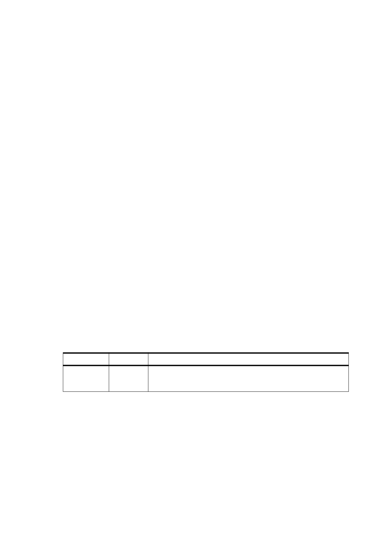
Table 71 - Entries in a DeviceN Colour Space Attributes Dictionary
Key
Type
Value
Subtype
name
(Optional; PDF 1.6) A name specifying the preferred treatment for the
colour space. Values shall be DeviceN or NChannel. Default value:
DeviceN.
161
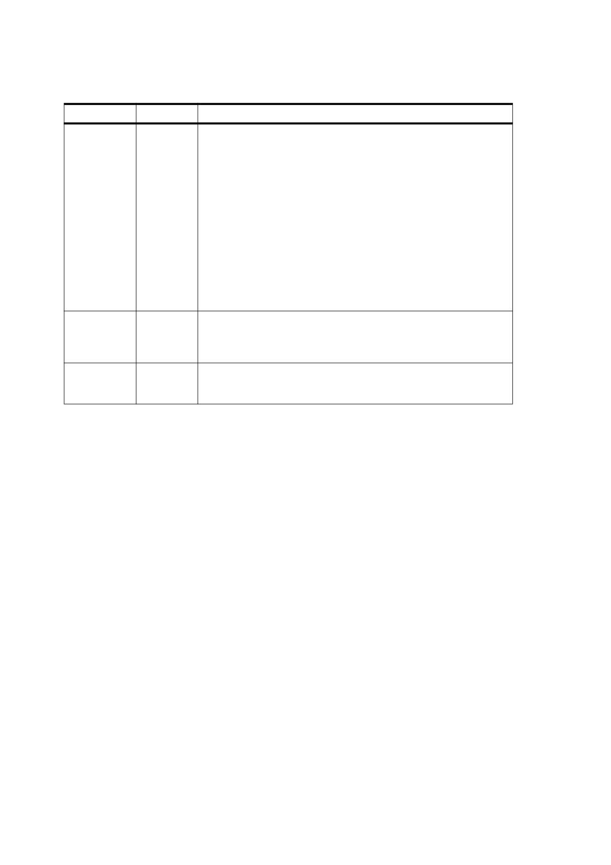
Table 71 - Entries in a DeviceN Colour Space Attributes Dictionary (continued)
Key
Type
Value
Colorants
dictionary
(Required if Subtype is NChannel and the colour space includes spot
colorants; otherwise optional) A dictionary describing the individual
colorants that shall be used in the DeviceN colour space. For each entry in
this dictionary, the key shall be a colorant name and the value shall be an
array defining a Separation colour space for that colorant (see 8.6.6.4,
"Separation Colour Spaces"). The key shall match the colorant name
given in that colour space.
This dictionary provides information about the individual colorants that
may be useful to some conforming readers. In particular, the alternate
colour space and tint transformation function of a Separation colour space
describe the appearance of that colorant alone, whereas those of a
DeviceN colour space describe only the appearance of its colorants in
combination.
If Subtype is NChannel, this dictionary shall have entries for all spot
colorants in this colour space. This dictionary may also include additional
colorants not used by this colour space.
Process
dictionary
(Required if Subtype is NChannel and the colour space includes
components of a process colour space, otherwise optional; PDF 1.6) A
dictionary (see Table 72) that describes the process colour space whose
components are included in this colour space.
MixingHints
dictionary
(Optional; PDF 1.6) A dictionary (see Table 73) that specifies optional
attributes of the inks that shall be used in blending calculations when used
as an alternative to the tint transformation function.
A value of NChannel for the Subtype entry indicates that some of the other entries in this dictionary are
required rather than optional. The Colorants entry specifies a colorants dictionary that contains entries for all
the spot colorants in the colour space; they shall be defined using individual Separation colour spaces. The
Process entry specifies a process dictionary (see Table 72) that identifies the process colour space that is
used by this colour space and the names of its components. It shall be present if Subtype is NChannel and the
colour space has process colour components. An NChannel colour space shall contain components from at
most one process colour space.
For colour spaces that have a value of NChannel for the Subtype entry in the attributes dictionary (see
Table 71), the following restrictions apply to process colours:
•
There may be colour components from at most one process colour space, which may be any device or
CIE-based colour space.
•
For a non-CMYK colour space, the names of the process components shall appear sequentially in the
names array, in the normal colour space order (for example, Red, Green, and Blue). However, the names
in the names array need not match the actual colour space names (for example, a Red component need
not be named Red).The mapping of names is specified in the process dictionary (see Table 72 and
discussion below), which shall be present.
•
Definitions for process colorants should not appear in the colorants dictionary. Any such definition shall be
ignored if the colorant is also present in the process dictionary. Any component not specified in the process
dictionary shall be considered to be a spot colorant.
•
For a CMYK colour space, a subset of the components may be present, and they may appear in any order
in the names array. The reserved names Cyan, Magenta, Yellow, and Black shall always be considered
to be process colours, which do not necessarily correspond to the colorants of a specific device; they need
not have entries in the process dictionary.
•
The values associated with the process components shall be stored in their natural form (that is,
subtractive colour values for CMYK and additive colour values for RGB), since they shall be interpreted
162
directly as process values by consumers making use of the process dictionary. (For additive colour spaces,
this is the reverse of how colour values are specified for DeviceN, as described above in the discussion of
the names parameter.)
The MixingHints entry in the attributes dictionary specifies a mixing hints dictionary (see Table 73) that
provides information about the characteristics of colorants that may be used in blending calculations when the
actual colorants are not available on the target device. Conforming readers need not use this information.
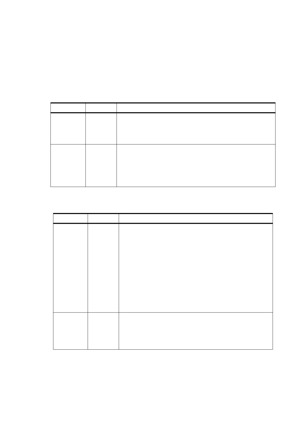
Table 72 - Entries in a DeviceN Process Dictionary
KEY
TYPE
VALUE
ColorSpace
name or
(Required) A name or array identifying the process colour space, which
array
may be any device or CIE-based colour space. If an ICCBased colour
space is specified, it shall provide calibration information appropriate for
the process colour components specified in the names array of the
DeviceN colour space.
Components
array
(Required) An array of component names that correspond, in order, to the
components of the process colour space specified in ColorSpace. For
example, an RGB colour space shall have three names corresponding to
red, green, and blue. The names may be arbitrary (that is, not the same as
the standard names for the colour space components) and shall match
those specified in the names array of the DeviceN colour space, even if all
components are not present in the names array.
Table 73 - Entries in a DeviceN Mixing Hints Dictionary
Key
Type
Value
Solidities
dictionary
(Optional) A dictionary specifying the solidity of inks that shall be used in
blending calculations when used as an alternative to the tint
transformation function. For each entry, the key shall be a colorant
name, and the value shall be a number between 0.0 and 1.0. This
dictionary need not contain entries for all colorants used in this colour
space; it may also include additional colorants not used by this colour
space.
A value of 1.0 simulates an ink that completely covers the inks beneath;
a value of 0.0 simulates a transparent ink that completely reveals the
inks beneath. An entry with a key of Default specifies a value that shall
be used by all components in the associated DeviceN colour space for
which a solidity value is not explicitly provided. If Default is not present,
the default value for unspecified colorants shall be 0.0; conforming
readers may choose to use other values.
If this entry is present, PrintingOrder shall also be present.
PrintingOrd
array
(Required if Solidities is present) An array of colorant names,
er
specifying the order in which inks shall be laid down. Each component in
the names array of the DeviceN colour space shall appear in this array
(although the order is unrelated to the order specified in the names
array). This entry may also list colorants unused by this specific
DeviceN instance.
163
Table 73 - Entries in a DeviceN Mixing Hints Dictionary (continued)
Key
Type
Value
DotGain
dictionary
(Optional) A dictionary specifying the dot gain of inks that shall be used
in blending calculations when used as an alternative to the tint
transformation function. Dot gain (or loss) represents the amount by
which a printer’s halftone dots change as the ink spreads and is
absorbed by paper.
For each entry, the key shall be a colorant name, and the value shall be
a function that maps values in the range 0 to 1 to values in the range 0
to 1. The dictionary may list colorants unused by this specific DeviceN
instance and need not list all colorants. An entry with a key of Default
shall specify a function to be used by all colorants for which a dot gain
function is not explicitly specified.
Conforming readers may ignore values in this dictionary when other
sources of dot gain information are available, such as ICC profiles
associated with the process colour space or tint transformation functions
associated with individual colorants.
Each entry in the mixing hints dictionary refers to colorant names, which include spot colorants referenced by
the Colorants dictionary. Under some circumstances, they may also refer to one or more individual process
components called Cyan, Magenta, Yellow, or Black when DeviceCMYK is specified as the process colour
space in the process dictionary. However, applications shall ignore these process component entries if they can
obtain the information from an ICC profile.
NOTE 5
The mixing hints subdictionaries (as well as the colorants dictionary) may specify colorants that are not used in
any given instance of a DeviceN colour space. This allows them to be referenced from multiple DeviceN
colour spaces, which can produce smaller file sizes as well as consistent colour definitions across instances.
For consistency of colour, conforming readers should follow these guidelines:
•
The conforming reader shall apply either the specified tint transformation function or invoke the same
alternative blending algorithm for all DeviceN instances in the document.
NOTE 6
When the tint transformation function is used, the burden is on the conforming writer to guarantee that the
individual function definitions chosen for all DeviceN instances produce similar colour appearances throughout
the document.
•
Blending algorithms should produce a similar appearance for colours when they are used as separation
colours or as a component of a DeviceN colour space.
EXAMPLE 3
This example shows a DeviceN colour space consisting of three colour components named Orange,
Green, and None. In this example, the DeviceN colour space, object 30, has an attributes dictionary
whose Colorants entry is an indirect reference to object 45 (which might also be referenced by attributes
dictionaries of other DeviceN colour spaces). tintTransform1, whose definition is not shown, maps three
colour components (tints of the colorants Orange, Green, and None) to four colour components in the
alternate colour space, DeviceCMYK. tintTransform2 maps a single colour component (an orange tint) to
four components in DeviceCMYK. Likewise, tintTransform3 maps a green tint to DeviceCMYK, and
tintTransform4 maps a tint of PANTONE 131 to DeviceCMYK.
30 0 obj
% Colour space
[
/DeviceN
[ /Orange /Green /None ]
/DeviceCMYK
tintTransform1
<< /Colorants 45 0 R >>
]
endobj
164
EXAMPLE 4
45 0 obj
% Colorants dictionary
<<
/Orange
[
/Separation
/Orange
/DeviceCMYK
tintTransform2
]
/Green [ /Separation
/Green
/DeviceCMYK
tintTransform3
]
/PANTONE#20131 [ /Separation
/PANTONE#20131
/DeviceCMYK
tintTransform4
]
>>
endobj
NOTE 7
EXAMPLE 5 through EXAMPLE 8 show the use of NChannel colour spaces.
EXAMPLE 5
This example shows the use of calibrated CMYK process components. EXAMPLE 6 shows the use of
Lab process components.
10 0 obj
% Colour space
[
/DeviceN
[/Magenta /Spot1 /Yellow /Spot2]
alternateSpace
tintTransform1
<<
% Attributes dictionary
/Subtype /NChannel
/Process
<< /ColorSpace [/ICCBased CMYK_ICC profile ]
/Components [/Cyan /Magenta /Yellow /Black]
>>
/Colorants
<< /Spot1 [/Separation /Spot1 alternateSpace tintTransform2]
/Spot2 [/Separation /Spot2 alternateSpace tintTransform3]
>>
>>
]
endobj
EXAMPLE 6
10 0 obj
%Colour space
[ /DeviceN
[/L /a /b /Spot1 /Spot2]
alternateSpace
tintTransform1
<<
% Attributes dictionary
/Subtype /NChannel
/Process
<< /ColorSpace [ /Lab << /WhitePoint ... /Range ... >> ]
/Components [/L /a /b]
>>
/Colorants
<< /Spot1 [/Separation /Spot1 alternateSpace tintTransform2 ]
/Spot2 [/Separation /Spot2 alternateSpace tintTransform3]
>>
>>
]
EXAMPLE 7
This example shows the recommended convention for dealing with situations where a spot colorant and a
process colour component have the same name. Since the names array may not have duplicate names,
165
the process colours should be given different names, which are mapped to process components in the
Components entry of the process dictionary. In this case, Red refers to a spot colorant; ProcessRed,
ProcessGreen, and ProcessBlue are mapped to the components of an RGB colour space.
10 0 obj
% Colour space
[ /DeviceN
[/ProcessRed /ProcessGreen /ProcessBlue /Red]
alternateSpace
tintTransform1
<<
% Attributes dictionary
/Subtype /NChannel
/Process
<< /ColorSpace [ /ICCBased RGB_ICC profile ]
/Components [/ProcessRed /ProcessGreen /ProcessBlue]
>>
/Colorants
<< /Red [/Separation /Red alternateSpace tintTransform2 ] >>
>>
]
EXAMPLE 8
This example shows the use of a mixing hints dictionary.
10 0 obj
% Colour space
[/DeviceN
[/Magenta /Spot1 /Yellow /Spot2]
alternateSpace
tintTransform1
<<
/Subtype /NChannel
/Process
<< /ColorSpace [ /ICCBased CMYK_ICC profile ]
/Components [/Cyan /Magenta /Yellow /Black]
>>
/Colorants
<< /Spot1 [/Separation /Spot1 alternateSpace tintTransform2 ]
/Spot2 [/Separation /Spot2 alternateSpace tintTransform2 ]
>>
/MixingHints
<<
/Solidities
<< /Spot1 1.0
/Spot2 0.0
>>
/DotGain
<< /Spot1 function1
/Spot2 function2
/Magenta function3
/Yellow function4
>>
/PrintingOrder [/Magenta /Yellow /Spot1 /Spot2]
>>
>>
]
See 11.7.3, "Spot Colours and Transparency", for further discussion of the role of DeviceN colour spaces in the
transparent imaging model.
8.6.6.6
Multitone Examples
NOTE 1
The following examples illustrate various interesting and useful special cases of the use of Indexed and
DeviceN colour spaces in combination to produce multitone colours.
NOTE 2
EXAMPLE 1 and EXAMPLE 2 in this sub-clause illustrate the use of DeviceN to create duotone colour spaces.
166
EXAMPLE 1
In this example, an Indexed colour space maps index values in the range 0 to 255 to a duotone DeviceN
space in cyan and black. In effect, the index values are treated as if they were tints of the duotone space,
which are then mapped into tints of the two underlying colorants. Only the beginning of the lookup table
string for the Indexed colour space is shown; the full table would contain 256 two-byte entries, each
specifying a tint value for cyan and black, for a total of 512 bytes. If the alternate colour space of the
DeviceN space is selected, the tint transformation function (object 15 in the example) maps the two tint
components for cyan and black to the four components for a DeviceCMYK colour space by supplying
zero values for the other two components.
10 0 obj
%Colour space
[
/Indexed
[
/DeviceN
[ /Cyan /Black ]
/DeviceCMYK
15 0 R
]
255
< 6605 6806 6907 6B09 6C0A … >
]
endobj
15 0 obj
% Tint transformation function
<<
/FunctionType 4
/Domain [ 0.0 1.0
0.0 1.0 ]
/Range [ 0.0 1.0
0.0
1.0
0.0
1.0
0.0 1.0 ]
/Length 16
>>
stream
{ 0 0 3 -1 roll }
endstream
endobj
EXAMPLE 2
This example shows the definition of another duotone colour space, this time using black and gold
colorants (where gold is a spot colorant) and using a CalRGB space as the alternate colour space. This
could be defined in the same way as in the preceding example, with a tint transformation function that
converts from the two tint components to colours in the alternate CalRGB colour space.
30 0 obj
% Colour space
[ /Indexed
[ /DeviceN
[ /Black
/Gold ]
[
/CalRGB
<<
/WhitePoint [ 1.0 1.0 1.0 ]
/Gamma [ 2.2 2.2 2.2 ]
>>
]
35 0 R
% Tint transformation function
]
255
… Lookup table…
]
endobj
NOTE 3
Given a formula for converting any combination of black and gold tints to calibrated RGB, a 2-in, 3-out type 4
(PostScript calculator) function could be used for the tint transformation. Alternatively, a type 0 (sampled)
function could be used, but this would require a large number of sample points to represent the function
accurately; for example, sampling each input variable for 256 tint values between 0.0 and 1.0 would require
256 2 = 65,536 samples. But since the DeviceN colour space is being used as the base of an Indexed colour
space, there are actually only 256 possible combinations of black and gold tint values.
167
EXAMPLE 3
This example shows a more compact way to represent this information is to put the alternate colour
values directly into the lookup table alongside the DeviceN colour values.
10 0 obj
% Colour space
[
/Indexed
[ /DeviceN
[ /Black
/Gold /None /None /None ]
[
/CalRGB
<<
/WhitePoint [ 1.0 1.0 1.0 ]
/Gamma [ 2.2 2.2 2.2 ]
>>
]
20 0 R
% Tint transformation function
]
255
… Lookup table…
]
endobj
NOTE 4
In EXAMPLE 3 in this sub-clause, each entry in the lookup table has five components: two for the black and
gold colorants and three more (specified as None) for the equivalent CalRGB colour components. If the black
and gold colorants are available on the output device, the None components are ignored; if black and gold are
not available, the tint transformation function is used to convert a five-component colour into a three-
component equivalent in the alternate CalRGB colour space. But because, by construction, the third, fourth,
and fifth components are the CalRGB components, the tint transformation function can merely discard the first
two components and return the last three. This can be readily expressed with a type 4 (PostScript calculator)
function (see EXAMPLE 4 in this sub-clause).
EXAMPLE 4
This example shows a type 4 (PostScript calculator) function.
20 0 obj
% Tint transformation function
<<
/FunctionType 4
/Domain [ 0.0 1.0
0.0
1.0
0.0
1.0
0.0
1.0
0.0 1.0 ]
/Range [ 0.0 1.0
0.0
1.0
0.0 1.0 ]
/Length 27
>>
stream
{ 5
3 roll pop pop }
endstream
endobj
EXAMPLE 5
This example uses an extension of the techniques described above to produce the quadtone (four-
component) image shown in Figure L.7 in Annex L.
5 0 obj
% Image XObject
<<
/Type /XObject
/Subtype /Image
/Width 288
/Height 288
/ColorSpace 10 0 R
/BitsPerComponent 8
/Length 105278
/Filter
/ASCII85Decode
>>
stream
… Data for grayscale image…
endstream
endobj
10 0 obj
% Indexed colour space for image
[ /Indexed
15 0 R
% Base colour space
168
255
% Table has 256 entries
30 0 R
% Lookup table
]
endobj
15 0 obj
% Base colour space ( DeviceN ) for Indexed space
[
/DeviceN
[
/Black
% Four colorants (black plus three spot colours)
/PANTONE#20216#20CVC
/PANTONE#20409#20CVC
/PANTONE#202985#20CVC
/None
% Three components for alternate space
/None
/None
]
16 0 R
% Alternate colour space
20 0 R
% Tint transformation function
]
endobj
16 0 obj
% Alternate colour space for DeviceN space
[
/CalRGB
<< /WhitePoint [ 1.0 1.0 1.0 ] >>
]
endobj
20 0 obj
% Tint transformation function for DeviceN space
<<
/FunctionType 4
/Domain [ 0.0 1.0
0.0
1.0
0.0
1.0
0.0
1.0
0.0
1.0
0.0
1.0
0.0 1.0 ]
/Range [ 0.0 1.0
0.0
1.0
0.0 1.0 ]
/Length 44
>>
stream
{
7 3 roll
% Just discard first four values
pop pop pop pop
}
endstream
endobj
30 0 obj
% Lookup table for Indexed colour space
<<
/Length 1975
/Filter
[ /ASCII85Decode /FlateDecode ]
>>
stream
8;T1BB2"M7*!"psYBt1k\gY1T<D&tO]r*F7Hga*
… Additional data ( seven components for each table entry )…
endstream
endobj
NOTE 5
As in the preceding examples, an Indexed colour space based on a DeviceN space is used to paint the
grayscale image shown on the left in the plate with four colorants: black and three PANTONE spot colours. The
alternate colour space is a simple calibrated RGB. Thus, the DeviceN colour space has seven components:
the four desired colorants plus the three components of the alternate space. The example shows the image
XObject (see 8.9.5, "Image Dictionaries") representing the quadtone image, followed by the colour space used
to interpret the image data.
8.6.7
Overprint Control
The graphics state contains an overprint parameter, controlled by the OP and op entries in a graphics state
parameter dictionary. Overprint control is useful mainly on devices that produce true physical separations, but it
is available on some composite devices as well. Although the operation of this parameter is device-dependent,
169
it is described here rather than in the sub-clause on colour rendering, because it pertains to an aspect of
painting in device colour spaces that is important to many applications.
Any painting operation marks some specific set of device colorants, depending on the colour space in which
the painting takes place. In a Separation or DeviceN colour space, the colorants to be marked shall be
specified explicitly; in a device or CIE-based colour space, they shall be implied by the process colour model of
the output device (see clause 10, "Rendering"). The overprint parameter is a boolean flag that determines how
painting operations affect colorants other than those explicitly or implicitly specified by the current colour space.
If the overprint parameter is false (the default value), painting a colour in any colour space shall cause the
corresponding areas of unspecified colorants to be erased (painted with a tint value of 0.0). The effect is that
the colour at any position on the page is whatever was painted there last, which is consistent with the normal
painting behaviour of the opaque imaging model.
If the overprint parameter is true and the output device supports overprinting, erasing actions shall not be
performed; anything previously painted in other colorants is left undisturbed. Consequently, the colour at a
given position on the page may be a combined result of several painting operations in different colorants. The
effect produced by such overprinting is device-dependent and is not defined here.
NOTE 1
Not all devices support overprinting. Furthermore, many PostScript printers support it only when separations
are being produced, and not for composite output.
If overprinting is not supported, the value of the overprint parameter shall be ignored.
An additional graphics state parameter, the overprint mode (PDF 1.3), shall affect the interpretation of a tint
value of 0.0 for a colour component in a DeviceCMYK colour space when overprinting is enabled. This
parameter is controlled by the OPM entry in a graphics state parameter dictionary; it shall have an effect only
when the overprint parameter is true, as described above.
When colours are specified in a DeviceCMYK colour space and the native colour space of the output device is
also DeviceCMYK, each of the source colour components controls the corresponding device colorant directly.
Ordinarily, each source colour component value replaces the value previously painted for the corresponding
device colorant, no matter what the new value is; this is the default behaviour, specified by overprint mode 0.
When the overprint mode is 1 (also called nonzero overprint mode), a tint value of 0.0 for a source colour
component shall leave the corresponding component of the previously painted colour unchanged. The effect is
equivalent to painting in a DeviceN colour space that includes only those components whose values are
nonzero.
EXAMPLE
If the overprint parameter is true and the overprint mode is 1, the operation
0. 2 0. 3 0.0 1.0 k
is equivalent to
0. 2 0. 3 1.0 scn
in the colour space shown in this example.
10 0 obj
%Colour space
[
/DeviceN
[ /Cyan /Magenta /Black ]
/DeviceCMYK
15 0 R
]
endobj
15 0 obj
% Tint transformation function
<<
/FunctionType 4
/Domain [ 0.0 1.0
0.0
1.0
0.0 1.0 ]
/Range [ 0.0 1.0
0.0
1.0
0.0
1.0
0.0 1.0 ]
170
/Length 13
>>
stream
{ 0 exch }
endstream
endobj
Nonzero overprint mode shall apply only to painting operations that use the current colour in the graphics state
when the current colour space is DeviceCMYK (or is implicitly converted to DeviceCMYK; see 8.6.5.7, "Implicit
Conversion of CIE-Based Colour Spaces"). It shall not apply to the painting of images or to any colours that are
the result of a computation, such as those in a shading pattern or conversions from some other colour space. It
also shall not apply if the device’s native colour space is not DeviceCMYK; in that case, source colours shall be
converted to the device’s native colour space, and all components participate in the conversion, whatever their
values.
NOTE 2
This is shown explicitly in the alternate colour space and tint transformation function of the DeviceN colour
space (see EXAMPLE 3 in 8.6.6, "Special Colour Spaces").
See 11.7.4, "Overprinting and Transparency", for further discussion of the role of overprinting in the transparent
imaging model.
8.6.8
Colour Operators
Table 74 lists the PDF operators that control colour spaces and colour values. Also colour-related is the
graphics state operator ri, listed in Table 57 and discussed under 8.6.5.8, "Rendering Intents". Colour operators
may appear at the page description level or inside text objects (see Figure 9 in Annex L).
Table 74 - Colour Operators
Operands
Operator
Description
name
CS
(PDF 1.1) Set the current colour space to use for stroking operations. The
operand name shall be a name object. If the colour space is one that can
be specified by a name and no additional parameters (DeviceGray,
DeviceRGB, DeviceCMYK, and certain cases of Pattern), the name may
be specified directly. Otherwise, it shall be a name defined in the
ColorSpace subdictionary of the current resource dictionary (see 7.8.3,
"Resource Dictionaries"); the associated value shall be an array
describing the colour space (see 8.6.3, "Colour Space Families").
The names DeviceGray, DeviceRGB, DeviceCMYK, and Pattern
always identify the corresponding colour spaces directly; they never refer
to resources in the ColorSpace subdictionary.
The CS operator shall also set the current stroking colour to its initial
value, which depends on the colour space:
In a DeviceGray, DeviceRGB, CalGray, or CalRGB colour space, the
initial colour shall have all components equal to 0.0.
In a DeviceCMYK colour space, the initial colour shall be
[0.0
0.0 0.0 1.0 ].
In a Lab or ICCBased colour space, the initial colour shall have all
components equal to 0.0 unless that falls outside the intervals specified
by the space’s Range entry, in which case the nearest valid value shall be
substituted.
In an Indexed colour space, the initial colour value shall be 0.
In a Separation or DeviceN colour space, the initial tint value shall be 1.0
for all colorants.
In a Pattern colour space, the initial colour shall be a pattern object that
causes nothing to be painted.
name
cs
(PDF 1.1) Same as CS but used for nonstroking operations.
171
Table 74 - Colour Operators (continued)
Operands
Operator
Description
c
SC
(PDF 1.1) Set the colour to use for stroking operations in a device, CIE-
1… cn
based (other than ICCBased), or Indexed colour space. The number of
operands required and their interpretation depends on the current
stroking colour space:
For DeviceGray, CalGray, and Indexed colour spaces, one operand
shall be required (n = 1).
For DeviceRGB, CalRGB, and Lab colour spaces, three operands shall
be required (n = 3).
For DeviceCMYK, four operands shall be required (n = 4).
c
SCN
(PDF 1.2) Same as SC but also supports Pattern, Separation, DeviceN
1… cn
c
name
SCN
and ICCBased colour spaces.
1… cn
If the current stroking colour space is a Separation, DeviceN, or
ICCBased colour space, the operands c1… cn shall be numbers. The
number of operands and their interpretation depends on the colour space.
If the current stroking colour space is a Pattern colour space, name shall
be the name of an entry in the Pattern subdictionary of the current
resource dictionary
(see
7.8.3, "Resource Dictionaries"). For an
uncoloured tiling pattern (PatternType = 1 and PaintType = 2), c1… cn
shall be component values specifying a colour in the pattern’s underlying
colour space. For other types of patterns, these operands shall not be
specified.
c
sc
(PDF 1.1) Same as SC but used for nonstroking operations.
1… cn
c
scn
(PDF 1.2) Same as SCN but used for nonstroking operations.
1… cn
c
name
scn
1… cn
gray
G
Set the stroking colour space to DeviceGray (or the DefaultGray colour
space; see 8.6.5.6, "Default Colour Spaces") and set the gray level to use
for stroking operations. gray shall be a number between 0.0 (black) and
1.0 (white).
gray
g
Same as G but used for nonstroking operations.
r g b
RG
Set the stroking colour space to DeviceRGB (or the DefaultRGB colour
space; see 8.6.5.6, "Default Colour Spaces") and set the colour to use for
stroking operations. Each operand shall be a number between
0.0
(minimum intensity) and 1.0 (maximum intensity).
r g b
rg
Same as RG but used for nonstroking operations.
c m y k
K
Set the stroking colour space to DeviceCMYK (or the DefaultCMYK
colour space; see 8.6.5.6, "Default Colour Spaces") and set the colour to
use for stroking operations. Each operand shall be a number between 0.0
(zero concentration) and 1.0 (maximum concentration). The behaviour of
this operator is affected by the overprint mode (see 8.6.7, "Overprint
Control").
c m y k
k
Same as K but used for nonstroking operations.
Invoking operators that specify colours or other colour-related parameters in the graphics state is restricted in
certain circumstances. This restriction occurs when defining graphical figures whose colours shall be specified
separately each time they are used. Specifically, the restriction applies in these circumstances:
•
In any glyph description that uses the d1 operator (see 9.6.5, "Type 3 Fonts")
•
In the content stream of an uncoloured tiling pattern (see 8.7.3.3, "Uncoloured Tiling Patterns")
172
In these circumstances, the following actions cause an error:
•
Invoking any of the following operators:
CS
scn
K
cs
G
k
SC
g
ri
SCN
RG
sh
sc
rg
•
Invoking the gs operator with any of the following entries in the graphics state parameter dictionary:
TR
BG
UCR
TR2
BG2
UCR2
HT
•
Painting an image. However, painting an image mask (see 8.9.6.2, "Stencil Masking") shall be permitted
because it does not specify colours; instead, it designates places where the current colour shall be
painted.
8.7
Patterns
8.7.1
General
Patterns come in two varieties:
•
Tiling patterns consist of a small graphical figure (called a pattern cell) that is replicated at fixed horizontal
and vertical intervals to fill the area to be painted. The graphics objects to use for tiling shall be described
by a content stream.
•
Shading patterns define a gradient fill that produces a smooth transition between colours across the area.
The colour to use shall be specified as a function of position using any of a variety of methods.
NOTE 1
When operators such as S (stroke), f (fill), and Tj (show text) paint an area of the page with the current colour,
they ordinarily apply a single colour that covers the area uniformly. However, it is also possible to apply “paint”
that consists of a repeating graphical figure or a smoothly varying colour gradient instead of a simple colour.
Such a repeating figure or smooth gradient is called a pattern. Patterns are quite general, and have many
uses; for example, they can be used to create various graphical textures, such as weaves, brick walls,
sunbursts, and similar geometrical and chromatic effects.
NOTE 2
Older techniques such as defining a pattern by using character glyphs in a special font and painting them
repeatedly with the Tj operator should not be used. Another technique, defining patterns as halftone screens,
should not be used because the effects produced are device-dependent.
Patterns shall be specified in a special family of colour spaces named Pattern. These spaces shall use pattern
objects as the equivalent of colour values instead of the numeric component values used with other spaces. A
pattern object shall be a dictionary or a stream, depending on the type of pattern; the term pattern dictionary is
used generically throughout this sub-clause to refer to either a dictionary object or the dictionary portion of a
stream object. (Those pattern objects that are streams are specifically identified as such in the descriptions of
particular pattern types; unless otherwise stated, they are understood to be simple dictionaries instead.) This
sub-clause describes Pattern colour spaces and the specification of colour values within them.
NOTE 3
See 8.6, "Colour Spaces", for information about colour spaces and colour values in general and 11.6.7,
"Patterns and Transparency", for further discussion of the treatment of patterns in the transparent imaging
model.
173
8.7.2
General Properties of Patterns
A pattern dictionary contains descriptive information defining the appearance and properties of a pattern. All
pattern dictionaries shall contain an entry named PatternType, whose value identifies the kind of pattern the
dictionary describes: type 1 for a tiling pattern or type 2 for a shading pattern. The remaining contents of the
dictionary depend on the pattern type and are detailed in the sub-clauses on individual pattern types.
All patterns shall be treated as colours; a Pattern colour space shall be established with the CS or cs operator
just like other colour spaces, and a particular pattern shall be installed as the current colour with the SCN or
scn operator (see Table 74).
A pattern’s appearance is described with respect to its own internal coordinate system. Every pattern has a
pattern matrix, a transformation matrix that maps the pattern’s internal coordinate system to the default
coordinate system of the pattern’s parent content stream (the content stream in which the pattern is defined as
a resource). The concatenation of the pattern matrix with that of the parent content stream establishes the
pattern coordinate space, within which all graphics objects in the pattern shall be interpreted.
NOTE 1
If a pattern is used on a page, the pattern appears in the Pattern subdictionary of that page’s resource
dictionary, and the pattern matrix maps pattern space to the default (initial) coordinate space of the page.
Changes to the page’s transformation matrix that occur within the page’s content stream, such as rotation and
scaling, have no effect on the pattern; it maintains its original relationship to the page no matter where on the
page it is used. Similarly, if a pattern is used within a form XObject (see 8.10, "Form XObjects"), the pattern
matrix maps pattern space to the form’s default user space (that is, the form coordinate space at the time the
form is painted with the Do operator). A pattern may be used within another pattern; the inner pattern’s matrix
defines its relationship to the pattern space of the outer pattern.
NOTE 2
PostScript allows a pattern to be defined in one context but used in another. For example, a pattern might be
defined on a page (that is, its pattern matrix maps the pattern coordinate space to the user space of the page)
but be used in a form on that page, so that its relationship to the page is independent of each individual
placement of the form. PDF does not support this feature; in PDF, all patterns shall be local to the context in
which they are defined.
8.7.3
Tiling Patterns
8.7.3.1
General
A tiling pattern consists of a small graphical figure called a pattern cell. Painting with the pattern replicates the
cell at fixed horizontal and vertical intervals to fill an area. The effect is as if the figure were painted on the
surface of a clear glass tile, identical copies of which were then laid down in an array covering the area and
trimmed to its boundaries. This process is called tiling the area.
The pattern cell can include graphical elements such as filled areas, text, and sampled images. Its shape need
not be rectangular, and the spacing of tiles can differ from the dimensions of the cell itself. When performing
painting operations such as S (stroke) or f (fill), the conforming reader shall paint the cell on the current page as
many times as necessary to fill an area. The order in which individual tiles (instances of the cell) are painted is
unspecified and unpredictable; figures on adjacent tiles should not overlap.
The appearance of the pattern cell shall be defined by a content stream containing the painting operators
needed to paint one instance of the cell. Besides the usual entries common to all streams (see Table 5), this
stream’s dictionary may contain the additional entries listed in Table 75.
Table 75 - Additional Entries Specific to a Type 1 Pattern Dictionary
Key
Type
Value
Type
name
(Optional) The type of PDF object that this dictionary describes; if
present, shall be Pattern for a pattern dictionary.
PatternType
integer
(Required) A code identifying the type of pattern that this dictionary
describes; shall be 1 for a tiling pattern.
174
Table 75 - Additional Entries Specific to a Type 1 Pattern Dictionary (continued)
Key
Type
Value
PaintType
integer
(Required) A code that determines how the colour of the pattern cell
shall be specified:
a) Coloured tiling pattern. The pattern’s content stream shall specify
the colours used to paint the pattern cell. When the content
stream begins execution, the current colour is the one that was
initially in effect in the pattern’s parent content stream. This is
similar to the definition of the pattern matrix; see 8.7.2, "General
Properties of Patterns".
b) Uncoloured tiling pattern. The pattern’s content stream shall not
specify any colour information. Instead, the entire pattern cell is
painted with a separately specified colour each time the pattern is
used. Essentially, the content stream describes a stencil through
which the current colour shall be poured. The content stream
shall not invoke operators that specify colours or other colour-
related parameters in the graphics state; otherwise, an error
occurs (see 8.6.8, "Colour Operators"). The content stream may
paint an image mask, however, since it does not specify any
colour information (see 8.9.6.2, "Stencil Masking").
TilingType
integer
(Required) A code that controls adjustments to the spacing of tiles
relative to the device pixel grid:
a) Constant spacing. Pattern cells shall be spaced
consistently—that is, by a multiple of a device pixel. To achieve
this, the conforming reader may need to distort the pattern cell
slightly by making small adjustments to XStep, YStep, and the
transformation matrix. The amount of distortion shall not exceed 1
device pixel.
b) No distortion. The pattern cell shall not be distorted, but the
spacing between pattern cells may vary by as much as 1 device
pixel, both horizontally and vertically, when the pattern is painted.
This achieves the spacing requested by XStep and YStep on
average but not necessarily for each individual pattern cell.
c) Constant spacing and faster tiling. Pattern cells shall be spaced
consistently as in tiling type
1 but with additional distortion
permitted to enable a more efficient implementation.
BBox
rectangle
(Required) An array of four numbers in the pattern coordinate system
giving the coordinates of the left, bottom, right, and top edges,
respectively, of the pattern cell’s bounding box. These boundaries
shall be used to clip the pattern cell.
XStep
number
(Required) The desired horizontal spacing between pattern cells,
measured in the pattern coordinate system.
YStep
number
(Required) The desired vertical spacing between pattern cells,
measured in the pattern coordinate system.
NOTE
XStep and YStep may differ from the dimensions of the
pattern cell implied by the BBox entry. This allows tiling
with irregularly shaped figures.
XStep and YStep may be either positive or negative but shall not be
zero.
Resources
dictionary
(Required) A resource dictionary that shall contain all of the named
resources required by the pattern’s content stream
(see
7.8.3,
"Resource Dictionaries").
Matrix
array
(Optional) An array of six numbers specifying the pattern matrix (see
8.7.2, "General Properties of Patterns"). Default value: the identity
matrix [ 1 0 0 1 0 0 ].
175
The pattern dictionary’s BBox, XStep, and YStep values shall be interpreted in the pattern coordinate system,
and the graphics objects in the pattern’s content stream shall be defined with respect to that coordinate system.
The placement of pattern cells in the tiling is based on the location of one key pattern cell, which is then
displaced by multiples of XStep and YStep to replicate the pattern. The origin of the key pattern cell coincides
with the origin of the pattern coordinate system. The phase of the tiling can be controlled by the translation
components of the Matrix entry in the pattern dictionary.
Prior to painting with a tiling pattern, the conforming writer shall establish the pattern as the current colour in the
graphics state. Subsequent painting operations tile the painted areas with the pattern cell described by the
pattern’s content stream. To obtain the pattern cell, the conforming reader shall perform these steps:
a) Saves the current graphics state (as if by invoking the q operator)
b) Installs the graphics state that was in effect at the beginning of the pattern’s parent content stream, with the current
transformation matrix altered by the pattern matrix as described in 8.7.2, "General Properties of Patterns"
c) Paints the graphics objects specified in the pattern’s content stream
d) Restores the saved graphics state (as if by invoking the Q operator)
NOTE
The pattern’s content stream should not set any of the device-dependent parameters in the graphics state (see
Table 53) because it may result in incorrect output.
8.7.3.2
Coloured Tiling Patterns
A coloured tiling pattern is a pattern whose colour is self-contained. In the course of painting the pattern cell,
the pattern’s content stream explicitly sets the colour of each graphical element it paints. A single pattern cell
may contain elements that are painted different colours; it may also contain sampled grayscale or colour
images. This type of pattern is identified by a pattern type of 1 and a paint type of 1 in the pattern dictionary.
When the current colour space is a Pattern space, a coloured tiling pattern shall be selected as the current
colour by supplying its name as the single operand to the SCN or scn operator. This name shall be the key of
an entry in the Pattern subdictionary of the current resource dictionary (see 7.8.3, "Resource Dictionaries"),
whose value shall be the stream object representing the pattern. Since the pattern defines its own colour
information, no additional operands representing colour components shall be specified to SCN or scn.
EXAMPLE 1
If P1 is the name of a pattern resource in the current resource dictionary, the following code establishes it
as the current nonstroking colour:
/Pattern cs
/P1 scn
NOTE 1
Subsequent executions of nonstroking painting operators, such as f (fill), Tj (show text), or Do (paint external
object) with an image mask, use the designated pattern to tile the areas to be painted.
NOTE 2
The following defines a page (object 5) that paints three circles and a triangle using a coloured tiling pattern
(object 15) over a yellow background. The pattern consists of the symbols for the four suits of playing cards
(spades, hearts, diamonds, and clubs), which are character glyphs taken from the ZapfDingbats font (see D.6,
"ZapfDingbats Set and Encoding"); the pattern’s content stream specifies the colour of each glyph. Figure L.8
in Annex L shows the results.
EXAMPLE 2
5 0 obj
% Page object
<<
/Type /Page
/Parent 2 0 R
/Resources 10 0 R
/Contents 30 0 R
/CropBox [ 0 0 225 225 ]
>>
endobj
10 0 obj
% Resource dictionary for page
<<
/Pattern
<< /P1 15 0 R >>
176
>>
endobj
15 0 obj
% Pattern definition
<<
/Type /Pattern
/PatternType 1
% Tiling pattern
/PaintType 1
% Coloured
/TilingType
2
/BBox [ 0 0 100 100 ]
/XStep 100
/YStep 100
/Resources 16 0 R
/Matrix
[0.4
0.0 0.0 0.4 0.0 0.0 ]
/Length 183
>>
stream
BT
% Begin text object
/F1
1 Tf
% Set text font and size
64 0 0 64 7.1771 2.4414 Tm
% Set text matrix
0 Tc
% Set character spacing
0 Tw
% Set word spacing
1.0 0.0 0.0 rg
% Set nonstroking colour to red
( \001 ) Tj
% Show spade glyph
0.7478 -0.007 TD
% Move text position
0.0 1.0 0.0 rg
% Set nonstroking colour to green
( \002 ) Tj
% Show heart glyph
-0.7323 0.7813 TD
% Move text position
0.0 0.0 1.0 rg
% Set nonstroking colour to blue
( \003 ) Tj
% Show diamond glyph
0.6913 0.007 TD
% Move text position
0.0 0.0 0.0 rg
% Set nonstroking colour to black
( \004 ) Tj
% Show club glyph
ET
% End text object
endstream
endobj
16 0 obj
% Resource dictionary for pattern
<<
/Font << /F1 20 0 R >>
>>
endobj
20 0 obj
% Font for pattern
<<
/Type /Font
/Subtype /Type1
/Encoding 21 0 R
/BaseFont /ZapfDingbats
>>
endobj
21 0 obj
% Font encoding
<<
/Type /Encoding
/Differences
[1
/a109 /a110 /a111 /a112 ]
>>
endobj
30 0 obj
% Contents of page
<<
/Length 1252 >>
stream
0.0 G
% Set stroking colour to black
177
1.0 1.0 0.0 rg
% Set nonstroking colour to yellow
25 175 175 -150 re
% Construct rectangular path
f
% Fill path
/Pattern cs
% Set pattern colour space
/P1 scn
% Set pattern as nonstroking colour
99.92 49.92 m
% Start new path
99.92 77.52 77.52 99.92 49.92 99.92 c
% Construct lower-left circle
22.32 99.92 -0.08 77.52 -0.08 49.92 c
-0.08 22.32 22.32 -0.08 49.92 -0.08 c
77.52 -0.08 99.92 22.32 99.92 49.92 c
B
% Fill and stroke path
224.96 49.92 m
% Start new path
224.96 77.52 202.56 99.92 174.96 99.92 c
% Construct lower-right circle
147.36 99.92 124.96 77.52 124.96 49.92 c
124.96 22.32 147.36 -0.08 174.96 -0.08 c
202.56 -0.08 224.96 22.32 224.96 49.92 c
B
% Fill and stroke path
87.56 201.70 m
% Start new path
63.66 187.90 55.46 157.32 69.26 133.40 c
% Construct upper circle
83.06 109.50 113.66 101.30 137.56 115.10 c
161.46 128.90 169.66 159.50 155.86 183.40 c
142.06 207.30 111.46 215.50 87.56 201.70 c
B
% Fill and stroke path
50 50 m
% Start new path
175 50 l
% Construct triangular path
112.5 158.253 l
b
% Close, fill, and stroke path
endstream
endobj
NOTE 3
Several features of EXAMPLE 2 in this sub-clause are noteworthy:
The three circles and the triangle are painted with the same pattern. The pattern cells align, even though the
circles and triangle are not aligned with respect to the pattern cell. For example, the position of the blue
diamonds varies relative to the three circles.
The pattern cell does not completely cover the tile: it leaves the spaces between the glyphs unpainted. When
the tiling pattern is used as a colour, the existing background (the yellow rectangle) shows through these
unpainted areas.
8.7.3.3
Uncoloured Tiling Patterns
An uncoloured tiling pattern is a pattern that has no inherent colour: the colour shall be specified separately
whenever the pattern is used. It provides a way to tile different regions of the page with pattern cells having the
same shape but different colours. This type of pattern shall be identified by a pattern type of 1 and a paint type
of 2 in the pattern dictionary. The pattern’s content stream shall not explicitly specify any colours; it may paint
an image mask (see 8.9.6.2, "Stencil Masking") but no other kind of image.
A Pattern colour space representing an uncoloured tiling pattern shall have a parameter: an object identifying
the underlying colour space in which the actual colour of the pattern shall be specified. The underlying colour
space shall be given as the second element of the array that defines the Pattern colour space.
EXAMPLE 1
The array
[ /Pattern
/DeviceRGB ]
defines a Pattern colour space with DeviceRGB as its underlying colour space.
178
NOTE
The underlying colour space cannot be another Pattern colour space.
Operands supplied to the SCN or scn operator in such a colour space shall include a colour value in the
underlying colour space, specified by one or more numeric colour components, as well as the name of a
pattern object representing an uncoloured tiling pattern.
EXAMPLE 2
If the current resource dictionary (see 7.8.3, "Resource Dictionaries") defines Cs3 as the name of a
ColorSpace resource whose value is the Pattern colour space shown above and P2 as a Pattern
resource denoting an uncoloured tiling pattern, the code
/Cs3 cs
0.30 0.75 0.21 /P2 scn
establishes Cs3 as the current nonstroking colour space and P2 as the current nonstroking colour, to be
painted in the colour represented by the specified components in the DeviceRGB colour space.
Subsequent executions of nonstroking painting operators, such as f (fill), Tj (show text), and Do (paint
external object) with an image mask, use the designated pattern and colour to tile the areas to be painted.
The same pattern can be used repeatedly with a different colour each time.
EXAMPLE 3
This example is similar to EXAMPLE 2 in 8.7.3.2, except that it uses an uncoloured tiling pattern to paint
the three circles and the triangle, each in a different colour (see Figure L.9 in Annex L). To do so, it
supplies four operands each time it invokes the scn operator: three numbers denoting the colour
components in the underlying DeviceRGB colour space, along with the name of the pattern.
5 0 obj
% Page object
<<
/Type /Page
/Parent 2 0 R
/Resources 10 0 R
/Contents 30 0 R
/CropBox [ 0 0 225 225 ]
>>
endobj
10 0 obj
% Resource dictionary for page
<<
/ColorSpace << /Cs12 12 0 R >>
/Pattern
<< /P1 15 0 R >>
>>
endobj
12 0 obj
%Colour space
[ /Pattern
/DeviceRGB ]
endobj
15 0 obj
% Pattern definition
<<
/Type /Pattern
/PatternType 1
% Tiling pattern
/PaintType 2
% Uncoloured
/TilingType
2
/BBox [ 0 0 100 100 ]
/XStep 100
/YStep 100
/Resources 16 0 R
/Matrix
[0.4
0.0 0.0 0.4 0.0 0.0 ]
/Length 127
>>
stream
BT
% Begin text object
/F1
1 Tf
% Set text font and size
64 0 0 64 7.1771 2.4414 Tm
% Set text matrix
0 Tc
% Set character spacing
0 Tw
% Set word spacing
( \001 ) Tj
% Show spade glyph
179
0.7478 -0.007 TD
% Move text position
( \002 ) Tj
% Show heart glyph
-0.7323 0.7813 TD
% Move text position
( \003 ) Tj
% Show diamond glyph
0.6913 0.007 TD
% Move text position
( \004 ) Tj
% Show club glyph
ET
% End text object
endstream
endobj
16 0 obj
% Resource dictionary for pattern
<<
/Font << /F1 20 0 R >>
>>
endobj
20 0 obj
% Font for pattern
<<
/Type /Font
/Subtype /Type1
/Encoding 21 0 R
/BaseFont /ZapfDingbats
>>
endobj
21 0 obj
% Font encoding
<<
/Type /Encoding
/Differences
[1
/a109 /a110 /a111 /a112 ]
>>
endobj
30 0 obj
% Contents of page
<<
/Length 1316 >>
stream
0.0 G
% Set stroking colour to black
1.0 1.0 0.0 rg
% Set nonstroking colour to yellow
25 175 175 -150 re
% Construct rectangular path
f
% Fill path
/Cs12 cs
% Set pattern colour space
0.77 0.20 0.00 /P1 scn
% Set nonstroking colour and pattern
99.92 49.92 m
% Start new path
99.92 77.52 77.52 99.92 49.92 99.92 c
% Construct lower-left circle
22.32 99.92 -0.08 77.52 -0.08 49.92 c
-0.08 22.32 22.32 -0.08 49.92 -0.08 c
77.52 -0.08 99.92 22.32 99.92 49.92 c
B
% Fill and stroke path
0.2 0.8 0.4 /P1 scn
% Change nonstroking colour
224.96 49.92 m
% Start new path
224.96 77.52 202.56 99.92 174.96 99.92 c
% Construct lower-right circle
147.36 99.92 124.96 77.52 124.96 49.92 c
124.96 22.32 147.36 -0.08 174.96 -0.08 c
202.56 -0.08 224.96 22.32 224.96 49.92 c
B
% Fill and stroke path
0.3 0.7 1.0 /P1 scn
% Change nonstroking colour
87.56 201.70 m
% Start new path
63.66 187.90 55.46 157.30 69.26 133.40 c
% Construct upper circle
83.06 109.50 113.66 101.30 137.56 115.10 c
161.46 128.90 169.66 159.50 155.86 183.40 c
142.06 207.30 111.46 215.50 87.56 201.70 c
B
% Fill and stroke path
180
0.5 0.2 1.0 /P1 scn
% Change nonstroking colour
50 50 m
% Start new path
175 50 l
% Construct triangular path
112.5 158.253 l
b
% Close, fill, and stroke path
endstream
endobj
8.7.4
Shading Patterns
8.7.4.1
General
Shading patterns (PDF 1.3) provide a smooth transition between colours across an area to be painted,
independent of the resolution of any particular output device and without specifying the number of steps in the
colour transition. Patterns of this type shall be described by pattern dictionaries with a pattern type of 2.
Table 76 shows the contents of this type of dictionary.
Table 76 - Entries in a Type 2 Pattern Dictionary
Key
Type
Value
Type
name
(Optional) The type of PDF object that this dictionary describes; if
present, shall be Pattern for a pattern dictionary.
PatternType
integer
(Required) A code identifying the type of pattern that this dictionary
describes; shall be 2 for a shading pattern.
Shading
dictionary
(Required) A shading object (see below) defining the shading pattern’s
or stream
gradient fill. The contents of the dictionary shall consist of the entries in
Table 78 and those in one of Tables 79 to 84.
Matrix
array
(Optional) An array of six numbers specifying the pattern matrix (see
8.7.2, "General Properties of Patterns"). Default value: the identity
matrix [ 1 0 0 1 0 0 ].
ExtGState
dictionary
(Optional) A graphics state parameter dictionary (see 8.4.5, "Graphics
State Parameter Dictionaries") containing graphics state parameters to
be put into effect temporarily while the shading pattern is painted. Any
parameters that are so specified shall be inherited from the graphics
state that was in effect at the beginning of the content stream in which
the pattern is defined as a resource.
The most significant entry is Shading, whose value shall be a shading object defining the properties of the
shading pattern’s gradient fill. This is a complex “paint” that determines the type of colour transition the shading
pattern produces when painted across an area. A shading object shall be a dictionary or a stream, depending
on the type of shading; the term shading dictionary is used generically throughout this sub-clause to refer to
either a dictionary object or the dictionary portion of a stream object. (Those shading objects that are streams
are specifically identified as such in the descriptions of particular shading types; unless otherwise stated, they
are understood to be simple dictionaries instead.)
By setting a shading pattern as the current colour in the graphics state, a PDF content stream may use it with
painting operators such as f (fill), S (stroke), Tj (show text), or Do (paint external object) with an image mask to
paint a path, character glyph, or mask with a smooth colour transition. When a shading is used in this way, the
geometry of the gradient fill is independent of that of the object being painted.
8.7.4.2
Shading Operator
When the area to be painted is a relatively simple shape whose geometry is the same as that of the gradient fill
itself, the sh operator may be used instead of the usual painting operators. sh accepts a shading dictionary as
an operand and applies the corresponding gradient fill directly to current user space. This operator does not
181
require the creation of a pattern dictionary or a path and works without reference to the current colour in the
graphics state. Table 77 describes the sh operator.
NOTE
Patterns defined by type 2 pattern dictionaries do not tile. To create a tiling pattern containing a gradient fill,
invoke the sh operator from within the content stream of a type 1 (tiling) pattern.
Table 77 - Shading Operator
Operands
Operator
Description
name
sh
(PDF 1.3) Paint the shape and colour shading described by a shading
dictionary, subject to the current clipping path. The current colour in the
graphics state is neither used nor altered. The effect is different from that of
painting a path using a shading pattern as the current colour.
name is the name of a shading dictionary resource in the Shading
subdictionary of the current resource dictionary
(see
7.8.3, "Resource
Dictionaries"). All coordinates in the shading dictionary are interpreted
relative to the current user space. (By contrast, when a shading dictionary is
used in a type 2 pattern, the coordinates are expressed in pattern space.) All
colours are interpreted in the colour space identified by the shading
dictionary’s ColorSpace entry (see Table 78). The Background entry, if
present, is ignored.
This operator should be applied only to bounded or geometrically defined
shadings. If applied to an unbounded shading, it paints the shading’s
gradient fill across the entire clipping region, which may be time-consuming.
8.7.4.3
Shading Dictionaries
A shading dictionary specifies details of a particular gradient fill, including the type of shading to be used, the
geometry of the area to be shaded, and the geometry of the gradient fill. Various shading types are available,
depending on the value of the dictionary’s ShadingType entry:
•
Function-based shadings (type 1) define the colour of every point in the domain using a mathematical
function (not necessarily smooth or continuous).
•
Axial shadings (type 2) define a colour blend along a line between two points, optionally extended beyond
the boundary points by continuing the boundary colours.
•
Radial shadings (type 3) define a blend between two circles, optionally extended beyond the boundary
circles by continuing the boundary colours. This type of shading is commonly used to represent three-
dimensional spheres and cones.
•
Free-form Gouraud-shaded triangle meshes (type 4) define a common construct used by many three-
dimensional applications to represent complex coloured and shaded shapes. Vertices are specified in free-
form geometry.
•
Lattice-form Gouraud-shaded triangle meshes (type 5) are based on the same geometrical construct as
type 4 but with vertices specified as a pseudorectangular lattice.
•
Coons patch meshes (type 6) construct a shading from one or more colour patches, each bounded by four
cubic Bézier curves.
•
Tensor-product patch meshes (type 7) are similar to type 6 but with additional control points in each patch,
affording greater control over colour mapping.
NOTE 1
Table 78 shows the entries that all shading dictionaries share in common; entries specific to particular shading
types are described in the relevant sub-clause.
NOTE 2
The term target coordinate space, used in many of the following descriptions, refers to the coordinate space
into which a shading is painted. For shadings used with a type 2 pattern dictionary, this is the pattern
182
coordinate space, discussed in 8.7.2, "General Properties of Patterns". For shadings used directly with the sh
operator, it is the current user space.
Table 78 - Entries Common to All Shading Dictionaries
Key
Type
Value
ShadingType
integer
(Required) The shading type:
1 Function-based shading
2 Axial shading
3 Radial shading
4 Free-form Gouraud-shaded triangle mesh
5 Lattice-form Gouraud-shaded triangle mesh
6 Coons patch mesh
7 Tensor-product patch mesh
ColorSpace
name or
(Required) The colour space in which colour values shall be
array
expressed. This may be any device, CIE-based, or special colour
space except a Pattern space. See 8.7.4.4, "Colour Space: Special
Considerations" for further information.
Background
array
(Optional) An array of colour components appropriate to the colour
space, specifying a single background colour value. If present, this
colour shall be used, before any painting operation involving the
shading, to fill those portions of the area to be painted that lie outside
the bounds of the shading object.
NOTE
In the opaque imaging model, the effect is as if the
painting operation were performed twice: first with the
background colour and then with the shading.
NOTE
The background colour is applied only when the shading
is used as part of a shading pattern, not when it is painted
directly with the sh operator.
BBox
rectangle
(Optional) An array of four numbers giving the left, bottom, right, and
top coordinates, respectively, of the shading’s bounding box. The
coordinates shall be interpreted in the shading’s target coordinate
space. If present, this bounding box shall be applied as a temporary
clipping boundary when the shading is painted, in addition to the
current clipping path and any other clipping boundaries in effect at that
time.
AntiAlias
boolean
(Optional) A flag indicating whether to filter the shading function to
prevent aliasing artifacts.
NOTE
The shading operators sample shading functions at a rate
determined by the resolution of the output device.
Aliasing can occur if the function is not smooth—that is, if
it has a high spatial frequency relative to the sampling
rate. Anti-aliasing can be computationally expensive and
is usually unnecessary, since most shading functions are
smooth enough or are sampled at a high enough
frequency to avoid aliasing effects. Anti-aliasing may not
be implemented on some output devices, in which case
this flag is ignored.
Default value: false.
Shading types 4 to 7 shall be defined by a stream containing descriptive data characterizing the shading’s
gradient fill. In these cases, the shading dictionary is also a stream dictionary and may contain any of the
standard entries common to all streams (see Table 5). In particular, shall include a Length entry.
In addition, some shading dictionaries also include a Function entry whose value shall be a function object
(dictionary or stream) defining how colours vary across the area to be shaded. In such cases, the shading
183
dictionary usually defines the geometry of the shading, and the function defines the colour transitions across
that geometry. The function is required for some types of shading and optional for others. Functions are
described in detail in 7.10, "Functions".
NOTE 3
Discontinuous colour transitions, or those with high spatial frequency, may exhibit aliasing effects when painted
at low effective resolutions.
8.7.4.4
Colour Space: Special Considerations
8.7.4.4.1 General
Conceptually, a shading determines a colour value for each individual point within the area to be painted. In
practice, however, the shading may actually be used to compute colour values only for some subset of the
points in the target area, with the colours of the intervening points determined by interpolation between the
ones computed. Conforming readers are free to use this strategy as long as the interpolated colour values
approximate those defined by the shading to within the smoothness tolerance specified in the graphics state
(see 10.6.3, "Smoothness Tolerance"). The ColorSpace entry common to all shading dictionaries not only
defines the colour space in which the shading specifies its colour values but also determines the colour space
in which colour interpolation is performed.
NOTE 1
Some types of shading (4 to 7) perform interpolation on a parametric value supplied as input to the shading’s
colour function, as described in the relevant sub-clause. This form of interpolation is conceptually distinct from
the interpolation described here, which operates on the output colour values produced by the colour function
and takes place within the shading’s target colour space.
Gradient fills between colours defined by most shadings may be implemented using a variety of interpolation
algorithms, and these algorithms may be sensitive to the characteristics of the colour space.
NOTE 2
Linear interpolation, for example, may have observably different results when applied in a DeviceCMYK colour
space than in a Lab colour space, even if the starting and ending colours are perceptually identical. The
difference arises because the two colour spaces are not linear relative to each other.
Shadings shall be rendered according to the following rules:
•
If ColorSpace is a device colour space different from the native colour space of the output device, colour
values in the shading shall be converted to the native colour space using the standard conversion formulas
described in
10.3, "Conversions among Device Colour Spaces". To optimize performance, these
conversions may take place at any time (before or after any interpolation on the colour values in the
shading). Thus, shadings defined with device colour spaces may have colour gradient fills that are less
accurate and somewhat device-dependent. (This does not apply to axial and radial shadings—shading
types 2 and 3—because those shading types perform gradient fill calculations on a single variable and
then convert to parametric colours.)
•
If ColorSpace is a CIE-based colour space, all gradient fill calculations shall be performed in that space.
Conversion to device colours shall occur only after all interpolation calculations have been performed.
Thus, the colour gradients are device-independent for the colours generated at each point.
•
If ColorSpace is a Separation or DeviceN colour space, a colour conversion (to the alternate colour
space) occurs only if one or more of the specified colorants is not supported by the device. In that case,
gradient fill calculations shall be performed in the designated Separation or DeviceN colour space before
conversion to the alternate space. Thus, nonlinear tint transformation functions shall be accommodated for
the best possible representation of the shading.
•
If ColorSpace is an Indexed colour space, all colour values specified in the shading shall be immediately
converted to the base colour space. Depending on whether the base colour space is a device or CIE-
based space, gradient fill calculations shall be performed as stated above. Interpolation shall never occur
in an Indexed colour space, which is quantized and therefore inappropriate for calculations that assume a
184
continuous range of colours. For similar reasons, an Indexed colour space shall not be used in any
shading whose colour values are generated by a function; this rule applies to any shading dictionary that
contains a Function entry.
8.7.4.5
Shading Types
8.7.4.5.1 General
In addition to the entries listed in Table 78, all shading dictionaries have entries specific to the type of shading
they represent, as indicated by the value of their ShadingType entry. The following sub-clauses describe the
available shading types and the dictionary entries specific to each.
8.7.4.5.2 Type 1 (Function-Based) Shadings
In Type 1 (function-based) shadings, the colour at every point in the domain is defined by a specified
mathematical function. The function need not be smooth or continuous. This type is the most general of the
available shading types and is useful for shadings that cannot be adequately described with any of the other
types. Table 79 shows the shading dictionary entries specific to this type of shading, in addition to those
common to all shading dictionaries (see Table 78).
This type of shading shall not be used with an Indexed colour space.
Table 79 - Additional Entries Specific to a Type 1 Shading Dictionary
Key
Type
Value
Domain
array
(Optional) An array of four numbers [ xmin xmax ymin ymax ] specifying
the rectangular domain of coordinates over which the colour function(s)
are defined. Default value: [ 0.0 1.0
0.0 1.0 ].
Matrix
array
(Optional) An array of six numbers specifying a transformation matrix
mapping the coordinate space specified by the Domain entry into the
shading’s target coordinate space.
NOTE
To map the domain rectangle [ 0.0 1.0
0.0 1.0 ] to a 1-inch
square with lower-left corner at coordinates (100, 100) in
default user space, the Matrix value would be
[72
0 0 72 100 100 ].
Default value: the identity matrix [ 1
0 0 1 0 0 ].
Function
function
(Required) A 2-in, n-out function or an array of n 2-in, 1-out functions
(where n is the number of colour components in the shading dictionary’s
colour space). Each function’s domain shall be a superset of that of the
shading dictionary. If the value returned by the function for a given colour
component is out of range, it shall be adjusted to the nearest valid value.
The domain rectangle (Domain) establishes an internal coordinate space for the shading that is independent of
the target coordinate space in which it shall be painted. The colour function(s) (Function) specify the colour of
the shading at each point within this domain rectangle. The transformation matrix (Matrix) then maps the
domain rectangle into a corresponding rectangle or parallelogram in the target coordinate space. Points within
the shading’s bounding box (BBox) that fall outside this transformed domain rectangle shall be painted with the
shading’s background colour (Background); if the shading dictionary has no Background entry, such points
shall be left unpainted. If the function is undefined at any point within the declared domain rectangle, an error
may occur, even if the corresponding transformed point falls outside the shading’s bounding box.
8.7.4.5.3 Type 2 (Axial) Shadings
Type 2 (axial) shadings define a colour blend that varies along a linear axis between two endpoints and extends
indefinitely perpendicular to that axis. The shading may optionally be extended beyond either or both endpoints
185
by continuing the boundary colours indefinitely. Table 80 shows the shading dictionary entries specific to this
type of shading, in addition to those common to all shading dictionaries (see Table 78).
This type of shading shall not be used with an Indexed colour space.
Table 80 - Additional Entries Specific to a Type 2 Shading Dictionary
Key
Type
Value
Coords
array
(Required) An array of four numbers [ x0 y0 x1 y1 ] specifying the starting
and ending coordinates of the axis, expressed in the shading’s target
coordinate space.
Domain
array
(Optional) An array of two numbers [ t0 t1 ] specifying the limiting values of
a parametric variable t. The variable is considered to vary linearly
between these two values as the colour gradient varies between the
starting and ending points of the axis. The variable t becomes the input
argument to the colour function(s). Default value: [ 0.0 1.0 ].
Function
function
(Required) A 1-in, n-out function or an array of n 1-in, 1-out functions
(where n is the number of colour components in the shading dictionary’s
colour space). The function(s) shall be called with values of the
parametric variable t in the domain defined by the Domain entry. Each
function’s domain shall be a superset of that of the shading dictionary. If
the value returned by the function for a given colour component is out of
range, it shall be adjusted to the nearest valid value.
Extend
array
(Optional) An array of two boolean values specifying whether to extend
the shading beyond the starting and ending points of the axis,
respectively. Default value: [ false false ].
The colour blend shall be accomplished by linearly mapping each point (x, y) along the axis between the
endpoints (x0 , y0 ) and (x1 , y1 ) to a corresponding point in the domain specified by the shading dictionary’s
Domain entry. The points (0, 0) and (1, 0) in the domain correspond respectively to (x0 , y0 ) and (x1 , y1 ) on the
axis. Since all points along a line in domain space perpendicular to the line from (0, 0) to (1, 0) have the same
colour, only the new value of x needs to be computed:
(
x1
-
x0
)
×
(
x x0
)
+
(
y1
-
y0
)
×
(
y y0
)
x′
= ------------------------------------------------------------------------------------------------------
(x
-
x0
)2
+
(
y1
-
y0
)2
1
The value of the parametric variable t is then determined from x ¢ as follows:
•
For 0
£ x ¢ £ 1, t = t0 + (t1 - t0 )
¥ x ¢.
•
For x ¢ < 0, if the first element of the Extend array is true, then t = t0 ; otherwise, t is undefined and the
point shall be left unpainted.
•
For x ¢ > 1, if the second element of the Extend array is true, then t = t1 ; otherwise, t is undefined and the
point shall be left unpainted.
The resulting value of t shall be passed as input to the function(s) defined by the shading dictionary’s Function
entry, yielding the component values of the colour with which to paint the point (x, y).
NOTE
Figure L.10 in Annex L shows three examples of the use of an axial shading to fill a rectangle and display text.
The area to be filled extends beyond the shading’s bounding box. The shading is the same in all three cases,
except for the values of the Background and Extend entries in the shading dictionary. In the first example, the
shading is not extended at either end and no background colour is specified; therefore, the shading is clipped
to its bounding box at both ends. The second example still has no background colour specified, but the
shading is extended at both ends; the result is to fill the remaining portions of the filled area with the colours
186
defined at the ends of the shading. In the third example, the shading is extended at both ends and a
background colour is specified; therefore, the background colour is used for the portions of the filled area
beyond the ends of the shading.
8.7.4.5.4 Type 3 (Radial) Shadings
Type 3 (radial) shadings define a colour blend that varies between two circles. Shadings of this type are
commonly used to depict three-dimensional spheres and cones. Shading dictionaries for this type of shading
contain the entries shown in Table 81, as well as those common to all shading dictionaries (see Table 78).
This type of shading shall not be used with an Indexed colour space.
Table 81 - Additional Entries Specific to a Type 3 Shading Dictionary
Key
Type
Value
Coords
array
(Required) An array of six numbers
[x0 y0 r0 x1 y1 r1 ] specifying the
centres and radii of the starting and ending circles, expressed in the
shading’s target coordinate space. The radii r0 and r1 shall both be
greater than or equal to 0. If one radius is 0, the corresponding circle shall
be treated as a point; if both are 0, nothing shall be painted.
Domain
array
(Optional) An array of two numbers [ t0 t1 ] specifying the limiting values of
a parametric variable t. The variable is considered to vary linearly
between these two values as the colour gradient varies between the
starting and ending circles. The variable t becomes the input argument to
the colour function(s). Default value: [ 0.0
1.0 ].
Function
function
(Required) A 1-in, n-out function or an array of n 1-in, 1-out functions
(where n is the number of colour components in the shading dictionary’s
colour space). The function(s) shall be called with values of the
parametric variable t in the domain defined by the shading dictionary’s
Domain entry. Each function’s domain shall be a superset of that of the
shading dictionary. If the value returned by the function for a given colour
component is out of range, it shall be adjusted to the nearest valid value.
Extend
array
(Optional) An array of two boolean values specifying whether to extend
the shading beyond the starting and ending circles, respectively. Default
value: [ false false ].
The colour blend is based on a family of blend circles interpolated between the starting and ending circles that
shall be defined by the shading dictionary’s Coords entry. The blend circles shall be defined in terms of a
subsidiary parametric variable
t
-
t0
s
= --------------
t
-
t0
1
which varies linearly between 0.0 and 1.0 as t varies across the domain from t0 to t1 , as specified by the
dictionary’s Domain entry. The centre and radius of each blend circle shall be given by the following parametric
equations:
xc(s)
=
x0
+
s
×
(
x1
–
x0
)
yc(s)
=
y0
+
s
×
(
y1
–
y0
)
r(s)
=
r0
+
s
×
(
r1
–
r0
)
Each value of s between 0.0 and 1.0 determines a corresponding value of t, which is passed as the input
argument to the function(s) defined by the shading dictionary’s Function entry. This yields the component
values of the colour with which to fill the corresponding blend circle. For values of s not lying between 0.0 and
187
1.0, the boolean elements of the shading dictionary’s Extend array determine whether and how the shading is
extended. If the first of the two elements is true, the shading shall be extended beyond the defined starting
circle to values of s less than 0.0; if the second element is true, the shading shall be extended beyond the
defined ending circle to s values greater than 1.0.
NOTE 1
Either of the starting and ending circles may be larger than the other. If the shading is extended at the smaller
end, the family of blend circles continues as far as that value of s for which the radius of the blend circle
r (s) = 0. If the shading is extended at the larger end, the blend circles continue as far as that s value for which
r (s) is large enough to encompass the shading’s entire bounding box (BBox). Extending the shading can thus
cause painting to extend beyond the areas defined by the two circles themselves. The two examples in the
rightmost column of Figure L.11 in Annex L depict the results of extending the shading at the smaller and larger
ends, respectively.
Conceptually, all of the blend circles shall be painted in order of increasing values of s, from smallest to largest.
Blend circles extending beyond the starting circle shall be painted in the same colour defined by the shading
dictionary’s Function entry for the starting circle (t = t0 , s = 0.0). Blend circles extending beyond the ending
circle shall be painted in the colour defined for the ending circle (t = t1 , s = 1.0). The painting is opaque, with
the colour of each circle completely overlaying those preceding it. Therefore, if a point lies within more than one
blend circle, its final colour shall be that of the last of the enclosing circles to be painted, corresponding to the
greatest value of s.
NOTE 2
If one of the starting and ending circles entirely contains the other, the shading depicts a sphere, as in Figure
L.12 and Figure L.13 in Annex L. In Figure L.12 in Annex L, the inner circle has zero radius; it is the starting
circle in the figure on the left and the ending circle in the figure on the right. Neither shading is extended at
either the smaller or larger end. In Figure L.13 in Annex L, the inner circle in both figures has a nonzero radius
and the shading is extended at the larger end. In each plate, a background colour is specified for the figure on
the right but not for the figure on the left.
NOTE 3
If neither circle contains the other, the shading depicts a cone. If the starting circle is larger, the cone appears
to point out of the page. If the ending circle is larger, the cone appears to point into the page (see Figure L.11 in
Annex L).
EXAMPLE 1
This example paints the leaf-covered branch shown in Figure L.14 in Annex L. Each leaf is filled with the
same radial shading (object number 5). The colour function (object 10) is a stitching function (described in
7.10.4, "Type 3 (Stitching) Functions") whose two subfunctions (objects 11 and 12) are both exponential
interpolation functions (see 7.10.3, "Type 2 (Exponential Interpolation) Functions").
5 0 obj
% Shading dictionary
<<
/ShadingType 3
/ColorSpace /DeviceCMYK
/Coords [ 0.0 0.0 0.096 0.0 0.0 1.0 00]
% Concentric circles
/Function 10 0 R
/Extend [ true true ]
>>
endobj
10 0 obj
%Colour function
<<
/FunctionType 3
/Domain [ 0.0 1.0 ]
/Functions [ 11 0 R 12 0 R ]
/Bounds [ 0.708 ]
/Encode [ 1.0 0.0 0.0 1.0 ]
>>
endobj
11 0 obj
% First subfunction
<<
/FunctionType 2
/Domain [ 0.0 1.0 ]
/C0 [ 0.929 0.357 1.000 0.298 ]
/C1 [ 0.631 0.278 1.000 0.027 ]
/N 1.048
>>
endobj
188
12 0 obj
% Second subfunction
<<
/FunctionType 2
/Domain [ 0.0 1.0 ]
/C0 [ 0.929 0.357 1.000 0.298 ]
/C1 [ 0.941 0.400 1.000 0.102 ]
/N 1.374
>>
endobj
EXAMPLE 2
This example shows how each leaf shown in Figure L.14 in Annex L is drawn as a path and then filled
with the shading (where the name Sh1 is associated with object 5 by the Shading subdictionary of the
current resource dictionary; see 7.8.3, "Resource Dictionaries").
316.789 140.311 m
% Move to start of leaf
303.222 146.388 282.966 136.518 279.122 121.983 c
% Curved segment
277.322 120.182 l
% Straight line
285.125 122.688 291.441 121.716 298.156 119.386 c
% Curved segment
336.448 119.386 l
% Straight line
331.072 128.643 323.346 137.376 316.789 140.311 c
% Curved segment
W n
% Set clipping path
q
% Save graphics state
27.7843 0.0000 0.0000 -27.7843 310.2461 121.1521 cm
% Set matrix
/Sh1 sh
% Paint shading
Q
% Restore graphics state
8.7.4.5.5 Type 4 Shadings (Free-Form Gouraud-Shaded Triangle Meshes)
Type 4 shadings (free-form Gouraud-shaded triangle meshes) are commonly used to represent complex
coloured and shaded three-dimensional shapes. The area to be shaded is defined by a path composed entirely
of triangles. The colour at each vertex of the triangles is specified, and a technique known as Gouraud
interpolation is used to colour the interiors. The interpolation functions defining the shading may be linear or
nonlinear. Table 82 shows the entries specific to this type of shading dictionary, in addition to those common to
all shading dictionaries (see Table 78) and stream dictionaries (see Table 5).
Table 82 - Additional Entries Specific to a Type 4 Shading Dictionary
Key
Type
Value
BitsPerCoordinate
integer
(Required) The number of bits used to represent each vertex
coordinate. The value shall be 1, 2, 4, 8, 12, 16, 24, or 32.
BitsPerComponent
integer
(Required) The number of bits used to represent each colour
component. The value shall be 1, 2, 4, 8, 12, or 16.
BitsPerFlag
integer
(Required) The number of bits used to represent the edge flag for
each vertex (see below). The value of BitsPerFlag shall be 2, 4, or
8, but only the least significant 2 bits in each flag value shall be
used. The value for the edge flag shall be 0, 1, or 2.
Decode
array
(Required) An array of numbers specifying how to map vertex
coordinates and colour components into the appropriate ranges of
values. The decoding method is similar to that used in image
dictionaries (see 8.9.5.2, "Decode Arrays"). The ranges shall be
specified as follows:
[xmin xmax ymin ymax c1,min c1,max
… cn,min cn,max ]
Only one pair of c values shall be specified if a Function entry is
present.
189
Table 82 - Additional Entries Specific to a Type 4 Shading Dictionary (continued)
Key
Type
Value
Function
function
(Optional) A 1-in, n-out function or an array of n 1-in, 1-out functions
(where n is the number of colour components in the shading
dictionary’s colour space). If this entry is present, the colour data for
each vertex shall be specified by a single parametric variable rather
than by n separate colour components. The designated function(s)
shall be called with each interpolated value of the parametric
variable to determine the actual colour at each point. Each input
value shall be forced into the range interval specified for the
corresponding colour component in the shading dictionary’s
Decode array. Each function’s domain shall be a superset of that
interval. If the value returned by the function for a given colour
component is out of range, it shall be adjusted to the nearest valid
value.
This entry shall not be used with an Indexed colour space.
Unlike shading types 1 to 3, types 4 to 7 shall be represented as streams. Each stream contains a sequence of
vertex coordinates and colour data that defines the triangle mesh. In a type 4 shading, each vertex is specified
by the following values, in the order shown:
f x y c1… cn
where
f is the vertex’s edge flag (discussed below)
x and y are its horizontal and vertical coordinates
c1… cn are its colour components
All vertex coordinates shall be expressed in the shading’s target coordinate space. If the shading dictionary
includes a Function entry, only a single parametric value, t, shall be specified for each vertex in place of the
colour components c1… cn .
The edge flag associated with each vertex determines the way it connects to the other vertices of the triangle
mesh. A vertex va with an edge flag value fa = 0 begins a new triangle, unconnected to any other. At least two
more vertices (vb and vc ) shall be provided, but their edge flags shall be ignored. These three vertices define a
triangle (va , vb , vc ), as shown in Figure 24.
fa=0
(Start new triangle)
Previous
va
triangle
vb
vc
Figure 24 - Starting a New Triangle in a Free-form Gouraud-shaded Triangle Mesh
190
Subsequent triangles shall be defined by a single new vertex combined with two vertices of the preceding
triangle. Given triangle (va , vb , vc ), where vertex va precedes vertex vb in the data stream and vb precedes vc ,
a new vertex vd can form a new triangle on side vbc or side vac , as shown in Figure 25. (Side vab is assumed to
be shared with a preceding triangle and therefore is not available for continuing the mesh.) If the edge flag is
fd = 1 (side vbc ), the next vertex forms the triangle (vb , vc , vd ); if the edge flag is fd = 2 (side vac ), the next
vertex forms the triangle (va , vc , vd ). An edge flag of fd = 0 starts a new triangle, as described above.
fd =0
fd =1
fd =2
va
va
va
vd
One new
vertex
vb
vc
vb
vc
vb
vc
vd
One new
Three new
vertex
vd
vertices
ve
vf
Figure 25 - Connecting Triangles in a Free-form Gouraud-shaded Triangle Mesh
Complex shapes can be created by using the edge flags to control the edge on which subsequent triangles are
formed.
EXAMPLE
Figure 26 shows two simple examples. Mesh 1 begins with triangle 1 and uses the following edge flags to
draw each succeeding triangle:
1
(
fa = fb = fc
=
0
)
7
(
fi
=
2
)
2
(
fd
=
1
)
8
(
fj
=
2
)
3
(
fe
=
1
)
9
(
fk
=
2
)
4
(
ff
=
1
)
10
(
fl
=
1
)
5
(
fg
=
1
)
11
(fm
=
1
)
6
(fh
=
1
)
Mesh 2 again begins with triangle 1 and uses the following edge flags:
1
(
fa = fb = fc
=
0
)
4
(
ff
=
2
)
2
(
fd
=
1
)
5
(
fg
=
2
)
3
(
fe
=
2
)
6
(
fh
=
2
)
The stream shall provide vertex data for a whole number of triangles with appropriate edge flags; otherwise, an
error occurs.
191
va
vc
ve
vg
va
vc
vh
vh = va
1
3
5
1
2
vd
4
vf
6
6
vb
2
vb
vh
vg
vd
vm
vk
11
9
7
5
3
vm = vb
10
8
4
vl
vj
vi
vf
ve
vk = vd
Mesh 1
Mesh 2
Figure 26 - Varying the Value of the Edge Flag to Create Different Shapes
The data for each vertex consists of the following items, reading in sequence from higher-order to lower-order
bit positions:
•
An edge flag, expressed in BitsPerFlag bits
•
A pair of horizontal and vertical coordinates, expressed in BitsPerCoordinate bits each
•
A set of n colour components (where n is the number of components in the shading’s colour space),
expressed in BitsPerComponent bits each, in the order expected by the sc operator
Each set of vertex data shall occupy a whole number of bytes. If the total number of bits required is not divisible
by 8, the last data byte for each vertex is padded at the end with extra bits, which shall be ignored. The
coordinates and colour values shall be decoded according to the Decode array in the same way as in an image
dictionary (see 8.9.5.2, "Decode Arrays").
If the shading dictionary contains a Function entry, the colour data for each vertex shall be specified by a
single parametric value t rather than by n separate colour components. All linear interpolation within the triangle
mesh shall be done using the t values. After interpolation, the results shall be passed to the function(s)
specified in the Function entry to determine the colour at each point.
8.7.4.5.6 Type 5 Shadings (Lattice-Form Gouraud-Shaded Triangle Meshes)
Type 5 shadings (lattice-form Gouraud-shaded triangle meshes) are similar to type 4, but instead of using free-
form geometry, their vertices are arranged in a pseudorectangular lattice, which is topologically equivalent to a
rectangular grid. The vertices are organized into rows, which need not be geometrically linear (see Figure 27).
(i, j)
(i, j+1)
(i+1, j)
(i+1, j+1)
Ideal lattice
Pseudorectangular lattice
Figure 27 - Lattice-form Triangle Meshes
192