Volvo V60 Cross Country (2018 year). Manual - part 4
SAFETY
62
•
•
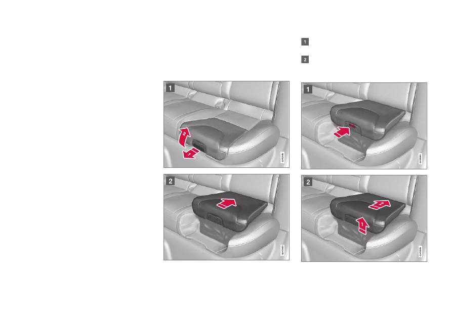
Integrated booster cushion – using
The Integrated booster cushion (p. 60) in the
rear seat can be folded up in two stages,
depending on the child's height and weight.
Stage 1
Pull the handle (1) forward and upward (2) to
release the booster cushion.
Press the booster cushion rearward to lock it
in position.
Stage 2