Volvo S60 (2018 year). Manual - part 17


  Index      Volvo     Volvo S60 - service manual 2018 year in english


Search            


Content   ..  15  16  17  18   ..


Volvo S60 (2018 year). Manual - part 17


STARTING AND DRIVING

}}

281

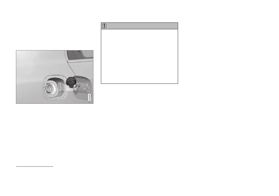
Refueling – opening/closing fuel

cap

If necessary, the fuel filler door can be opened
manually.

Opening/closing the fuel cap

Fuel vapor expands in hot weather. Open the filler
cap slowly.

After refueling, close the fuel filler cap by turning
it clockwise until it clicks into place.

CAUTION

Do not refuel with the engine running

12

.

Turn the ignition off or to position I. If the
ignition is on, an incorrect reading could
occur in the fuel gauge.

Avoid overfilling the fuel tank. Do not
press the handle on the filler nozzle more
than one extra time. Too much fuel in the
tank in hot weather conditions can cause
the fuel to overflow. Overfilling could also
cause damage to the emission control
systems.

Related information

Refueling – fuel requirements (p. 277)

Refueling – octane rating (p. 278)

Emission controls

Three-way catalytic converter

Keep your engine properly tuned. Certain
engine malfunctions, particularly involving the
electrical, fuel or distributor ignition systems,
may cause unusually high three-way catalytic
converter temperatures. Do not continue to
operate your vehicle if you detect engine
misfire, noticeable loss of power or other
unusual operating conditions, such as engine
overheating or backfiring. A properly tuned
engine will help avoid malfunctions that
could damage the three-way catalytic con-
verter.

Do not park your vehicle over combustible
materials, such as grass or leaves, which can
come into contact with the hot exhaust sys-
tem and cause such materials to ignite under
certain wind and weather conditions.

Excessive starter cranking (in excess of one
minute), or an intermittently firing or flooded
engine can cause three-way catalytic con-
verter or exhaust system overheating.

Remember that tampering or unauthorized
modifications to the engine, the Engine Con-
trol Module, or the vehicle may be illegal and
can cause three-way catalytic converter or
exhaust system overheating. This includes:
altering fuel injection settings or compo-

12

If the fuel filler cap is not closed tightly or if the engine is running when the vehicle is refueled, the Check Engine Light (malfunction indicator lamp) may indicate a fault. However, your vehicle's performance will

not be affected. Use only Volvo original or approved fuel filler caps.

||

STARTING AND DRIVING

* Option/accessory.

282

nents, altering emission system components
or location or removing components, and/or
repeated use of leaded fuel.

NOTE

Unleaded fuel is required for vehicles with
three-way catalytic converters.

Heated oxygen sensors

The heated oxygen sensors monitor the oxygen
content of the exhaust gases. Readings are fed
into a control module that continuously monitors
engine functions and controls fuel injection. The
ratio of fuel to air into the engine is continuously
adjusted for efficient combustion to help reduce
harmful emissions.

Related information

Information displays – warning symbols
(p. 69)

Engine and cooling system (p. 275)

Economical driving

Better driving economy may be obtained by
thinking ahead, avoiding rapid starts and stops
and adjusting the speed of your vehicle to imme-
diate traffic conditions.

Economical driving conserves natural
resources

Observe the following rules:

Bring the engine to normal operating tem-
perature as soon as possible by driving with
a light foot on the accelerator pedal for the
first few minutes of operation. A cold engine
uses more fuel and is subject to increased
wear.

Whenever possible, avoid using the vehicle
for driving short distances. This does not
allow the engine to reach normal operating
temperature.

Drive carefully and avoid rapid acceleration
and hard braking.

Use the transmission's Drive (D) position as
often as possible and avoid using kick-down.

Using the transmission's Sport mode

13

 may

increase fuel consumption somewhat. Use
the transmission's Drive (D) position as often
as possible. For additional information about
Sport mode, see Transmission – Geartronic
(p. 257).

Using the engine's optional Eco function can
help improve fuel economy. For additional
information, see ECO

* (p. 265).

Do not exceed posted speed limits.

Avoid carrying unnecessary items (extra load)
in the vehicle.

Maintain correct tire pressure. Check tire
pressure regularly (when tires are cold).

Remove snow tires when threat of snow or
ice has ended.

Note that roof racks, ski racks, etc, increase
air resistance and also fuel consumption.

At highway driving speeds, fuel consumption
will be lower with the air conditioning on and
the windows closed than with the air condi-
tioning off and the windows open.

Using the onboard trip computer's fuel con-
sumption modes can help you learn how to
drive more economically.

Other factors that decrease gas mileage are:

Dirty air cleaner

Dirty engine oil and clogged oil filter

Dragging brakes

Incorrect front end alignment

13

Certain models only.

STARTING AND DRIVING

}}

283

Some of the above mentioned items and others
are checked at the standard maintenance inter-
vals.

WARNING

Driving with the trunk open: Driving with the
trunk open could lead to poisonous exhaust
gases entering the passenger compartment. If
the trunk must be kept open for any reason,
proceed as follows:

Close the windows

Set the ventilation system control to air
flow to floor, windshield and side windows
and the blower control to its highest set-
ting.

Handling and roadholding

At the specified curb weight your vehicle has a
tendency to understeer, which means that the
steering wheel has to be turned more than might
seem appropriate for the curvature of a bend.
This ensures good stability and reduces the risk
of rear wheel skid. Remember that these proper-
ties can alter with the vehicle load. The heavier
the load in the trunk, the less the tendency to
understeer.

Vehicle load, tire design and inflation pres-
sure all affect vehicle handling. Therefore,
check that the tires are inflated to the rec-
ommended pressure according to the vehicle
load. Loads should be distributed so that

capacity weight or maximum permissible axle
loads are not exceeded.

At the specified curb weight your vehicle has
a tendency to understeer, which means that
the steering wheel has to be turned more
than might seem appropriate for the curva-
ture of a bend. This ensures good stability
and reduces the risk of rear wheel skid.
Remember that these properties can alter
with the vehicle load. The heavier the load in
the trunk, the less the tendency to under-
steer.

Related information

Climate – general information (p. 120)

Towing a trailer

When towing a trailer, always observe the legal
requirements of the state/province.

NOTE

For the maximum trailer and tongue weights
recommended by Volvo, see Weights (p. 371)

All Volvo models are equipped with energy-
absorbing shock-mounted bumpers. Trailer
hitch installation should not interfere with the
proper operation of this bumper system.

Trailer towing does not normally present any par-
ticular problems, but take into consideration:

Increase tire pressure to recommended full
pressure, see the tire inflation decal on the
driver's door opening.

When your vehicle is new, avoid towing heavy
trailers during the first 620 miles (1,000 km).

Maximum speed when towing a trailer:
50 mph (80 km/h).

Engine and transmission are subject to
increased loads. Therefore, engine coolant
temperature should be closely watched when
driving in hot climates or hilly terrain. Use a
lower gear and turn off the air conditioner if
the temperature gauge needle enters the red
range.

||

STARTING AND DRIVING

284

If the automatic transmission begins to over-
heat, a message will be displayed in the text
window.

Avoid overload and other abusive operation.

Hauling a trailer affects handling, durability,
and economy.

It is necessary to balance trailer brakes with
the towing vehicle brakes to provide a safe
stop (check and observe state/local regula-
tions).

Do not connect the trailer's brake system
directly to the vehicle's brake system.

More frequent vehicle maintenance is
required.

Remove the ball holder when the hitch is not
being used.

NOTE

When parking the vehicle with a trailer on
a hill, apply the parking brake before put-
ting the gear selector in P. Always follow
the trailer manufacturer's recommenda-
tions for wheel chocking.

When starting on a hill, put the gear
selector in D before releasing the parking
brake.

If you use the manual (Geartronic) shift
positions while towing a trailer, make sure
the gear you select does not put too
much strain on the engine (using too
high a gear).

The drawbar assembly/trailer hitch may
be rated for trailers heavier than the vehi-
cle is designed to tow. Please adhere to
Volvo's recommended trailer weights.

Avoid driving with a trailer on inclines of
more than 15%.

CAUTION

The maximum trailer weights listed are only
applicable for altitudes up to 3,280 ft
(1000 m) above sea level. With increasing
altitude the engine power and therefore the
car's climbing ability are impaired because of
the reduced air density, so the maximum
trailer weight has to be reduced accordingly.
The weight of the vehicle and trailer must be
reduced by 10% for every further 3,280 ft
(1,000 m) (or part thereof). When towing
5,000 lbs (2,250 kg) hill inclination is restric-
ted to 14%.

STARTING AND DRIVING

285

WARNING

Bumper-attached trailer hitches must not
be used on Volvos, nor should safety
chains be attached to the bumper.

Trailer hitches attaching to the vehicle
rear axle must not be used.

Never connect a trailer's hydraulic brake
system directly to the vehicle brake sys-
tem, nor a trailer's lighting system directly
to the vehicle lighting system. Consult
your nearest authorized Volvo retailer for
correct installation.

When towing a trailer, the trailer's safety
chains or wire must be correctly fastened
to the attachment points provided in the
trailer hitch on the vehicle. The safety
chain or wire must never be fastened to
or wound around the towing ball.

Trailer cable

An adapter is required if the vehicle's trailer hitch
has a 13-pin connector and the trailer has 7 pins.
Use an adapter cable approved by Volvo. Make
sure the cable does not drag on the ground.

Related information

Loading – general (p. 138)

Trailer Stability Assist (TSA)

Trailer Stability Assist is a system designed to
help stabilize a vehicle that is towing a trailer
when the vehicle and trailer have begun to sway
and is part of the stability system. For information
on the stability system, see Stability system –
introduction (p. 166)

Function

A vehicle towing a trailer may begin to sway for
various reasons. Normally this only occurs at high
speeds but, for example, if the trailer is overloa-
ded or if the load is unevenly distributed in the
trailer, there is risk of swaying at speeds between
approximately 45-55 mph (70-90 km/h).

Swaying may be caused by factors such as:

The vehicle and trailer are hit by a sudden,
strong crosswind

The vehicle and trailer are traveling on an
uneven road surface or drive over a bump

Sudden movements of the steering wheel

Facts about TSA

TSA intervenes at speeds above approxi-
mately 40 mph (60 km/h)

The stability system symbol in the instrument
panel will flash when TSA is working

If the driver switches off the stability system's
Spin Control function, TSA will also be
switched off (but will be on again the next
time the engine is started)

TSA may not intervene when the vehicle and
trailer begin to sway if the driver tries to com-
pensate for the swaying motion by moving
the steering wheel rapidly

How TSA works

Once swaying has begun, it can be very difficult
to stop, which makes it difficult to control the
vehicle and trailer.

The TSA system continuously monitors the vehi-
cle's movements, particularly lateral movement. If
the system detects a tendency to sway, the
brakes are applied individually on the front
wheels, which has a stabilizing effect on the vehi-
cle and trailer. This is often enough to enable the
driver to regain control of the vehicle.

If this is not adequate to stop the swaying motion,
the brakes are applied to all of the wheels on the
vehicle and on the trailer if it is equipped with
brakes, and engine power is temporarily reduced.
As the swaying motion begins to decrease and
the vehicle-trailer have once again become sta-
ble, TSA will now stop regulating the brakes/
engine power and the driver regains control of
the vehicle.

Related information

Towing a trailer (p. 283)

Loading – general (p. 138)

STARTING AND DRIVING

286

Towing the vehicle

Always check with state and local authorities
before attempting to tow another vehicle
because this type of towing is subject to regula-
tions regarding maximum towing speed, length
and type of towing device, lighting, etc.

1. With the remote key fully pressed into the

ignition slot

14

, press START/STOP ENGINE

for approximately 2 seconds to activate igni-
tion mode II.

2. The remote key must remain in the ignition

slot

15

 for the entire time that the vehicle is

being towed.

3. Keep the tow rope taut when the towing

vehicle slows down by applying light pressure
on the brake pedal. This will help prevent jar-
ring movements of the vehicle being towed.

4. Be prepared to apply the brakes to stop the

vehicle being towed.

CAUTION

General towing precautions:

Please check with state and local author-
ities before attempting this type of tow-
ing, as vehicles being towed are subject
to regulations regarding maximum towing
speed, length and type of towing device,
lighting, etc.

If the vehicle's battery is dead, see Jump
starting (p. 254) to provide current for
releasing the electric parking brake and
to move the gear selector from the P
position to N. If this is not possible, see
Transmission – shiftlock override (p. 259)
for information about manually overriding
the shiftlock system to move the gear
selector from P to N.

Maximum speed: 50 mph (80 km/h). Do
not exceed the maximum allowable tow-
ing speed.

Maximum distance with front wheels on
ground: 50 miles (80 km).

The vehicle should only be towed in the
forward direction.

Related information

Towing eyelet (p. 286)

Remote key – functions (p. 147)

Towing eyelet

When used, the towing eyelet should always be
securing attached.

Location of the towing eyelet

Removing the front/rear covers

14

Not necessary in vehicles with the optional keyless drive.

15

For vehicles with the optional keyless drive, the remote key must be in the vehicle.

STARTING AND DRIVING

}}

287

Attaching the towing eyelet

The towing eyelet is located under the floor
of the trunk. This eyelet must be screwed
into the positions provided on the right sides
of either the front or rear bumper (see illus-
tration).

There are two different types of covers over
the openings for the towing eyelet and they
have to be opened differently.

If the cover has a notch, insert a coin, etc.,
into the notch and pry open the edge of
the cover. Open the cover completely and
remove it.

If the cover has a mark along one edge or
in a corner, press the mark while prying
out the opposite side/corner using a coin,
etc. Open the cover and remove it.

Screw the towing eyelet in place, first by hand
and then using the tire iron until it is securely in
place.

After the vehicle has been towed, the eyelet
should be removed and returned to its storage
location.

Press the cover for the attachment point back
into position.

WARNING

When the vehicle is being towed, the igni-
tion should be in mode II (in mode I, all of
the vehicle's airbags are deactivated). For
more information, see Ignition modes
(p. 74)

Never remove the remote key from the
ignition slot when the vehicle is being
towed. For vehicles with keyless drive, the
remote key must remain inside the vehi-
cle.

The power brakes and power steering will
not function when the engine is not run-
ning. Approximately 5 times more pres-
sure will be required on the brake pedal
and the steering wheel will be considera-
bly harder to turn.

The towing eyelets must not be used for
pulling the vehicle out of a ditch or for
any similar purpose involving severe
strain.

Related information

Towing the vehicle (p. 286)

Towing by tow truck (p. 287)

Towing by tow truck

When necessary, call for professional help from
an authorized towing company. Volvo recom-
mends the use of flat bed equipment.

CAUTION

In certain conditions, the towing eyelet
may be used to pull the vehicle onto a
flatbed tow truck.

The vehicle's position and ground clear-
ance determine if it can be pulled up onto
a flatbed tow truck using the towing eye-
let.

If the angle of the tow truck’s ramp is too
steep or the ground clearance under the
vehicle is insufficient, damage could
occur by attempting to pull the vehicle
using the towing eyelet.

If necessary, lift the vehicle using the tow
truck’s lifting device.

WARNING

No person or object should be behind the tow
truck while the vehicle is being pulled up onto
the flatbed.

WHEELS AND TIRES

290

Tires – general information

Your vehicle is equipped with tires according to
the vehicle's tire information placard on the B-
pillar (the structural member at the side of the
vehicle, at the rear of the driver's door opening).

Introduction

CAUTION

Some Volvo models are equipped with an
Ultra High Performance tire and wheel com-
bination designed to provide maximum dry
pavement performance with consideration for
hydroplaning resistance. They may be more
susceptible to road hazard damage and,
depending on driving conditions, may achieve
a tread life of less than 20,000 miles (30,000
km). Even if this vehicle is equipped with Vol-
vo’s advanced AWD or stability system, these
tires are not designed for winter driving, and
should be replaced with winter tires when
weather conditions dictate.

The tires have good road holding characteristics
and offer good handling on dry and wet surfaces.
It should be noted however that the tires have
been developed to give these features on snow/
ice-free surfaces.

Most models are equipped with "all-season" tires,
which provide a somewhat higher degree of road
holding on slippery surfaces than tires without

the "all-season" rating. However, for optimum
road holding on icy or snow-covered roads, we
recommend suitable winter tires on all four
wheels.

When replacing tires, be sure that the new tires
are the same size designation, type (radial) and
preferably from the same manufacturer, on all
four wheels. Otherwise there is a risk of altering
the car's roadholding and handling characteris-
tics.

Tire rotation

Your vehicle has no required tire rotation. Tire
wear is affected by a number of factors such as
tire inflation, ambient temperature, driving style,
etc.

NOTE

If the tires are rotated, they should only
be moved from front to rear or vice versa.
They should never be rotated left to
right/right to left.

Ideally, tire rotation should be done the
first time after approximately 3,000 miles
(5,000 km) and thereafter at 6,000-mile
(10,000-km) intervals. Some customers
find that tire rotation may help to get
extra mileage from tire life.

Tire rotation should only be performed if
front/rear tire wear is fairly even and
tread height is above 1/16" (1.6 mm).

Related information

Tire specifications (p. 300)

Changing a wheel – direction of rotation
(p. 293)

Tires – tread wear indicator (p. 292)

WHEELS AND TIRES

291

Tires – storage and age

When storing complete wheels (tires mounted
on rims), they should be suspended off the floor
or placed on their sides on the floor.

New Tires

Remember that tires are perishable goods. As of
2000, the manufacturing week and year (Depart-
ment of Transportation (DOT) stamp) will be indi-
cated with 4 digits (e.g., 1513 means that the tire
illustrated was manufactured during week 15 of
2013).

Tire age

Tires degrade over time, even when they are not
being used. It is recommended that tires gener-
ally be replaced after 6 years of normal service.
Heat caused by hot climates, frequent high load-
ing conditions or Ultra Violet (U.V.) exposure can

accelerate the aging process. The temporary
spare

1

 should also be replaced at 6-year inter-

vals, even if it has never been used.

A tire's age can be determined by the DOT stamp
on the sidewall (see the illustration).

A tire with e.g., visible cracks or discoloration
should be replaced immediately.

Storing wheels and tires

When storing completes wheels (tires mounted
on rims), they should be suspended off the floor
or placed on their sides on the floor.

Tires not mounted on rims should be stored on
their sides or standing upright, but should not be
suspended.

CAUTION

Tires should preferably be stored in a cool,
dry, dark place, and should never be stored in
close proximity to solvents, gasoline, oils, etc.

WARNING

The wheel and tire sizes for your Volvo
are specified to meet stringent stability
and handling requirements. Unapproved
wheel/tire size combinations can nega-
tively affect your vehicle's stability and
handling.

Any damage caused by installation of
unapproved wheel/tire size combinations
will not be covered by your new vehicle
warranty. Volvo assumes no responsibility
for death, injury, or expenses that may
result from such installations.

Related information

Tire specifications (p. 300)

Tire specifications (p. 300)

Changing a wheel – direction of rotation
(p. 293)

Tires – tread wear indicator (p. 292)

1

Option or accessory on some models

WHEELS AND TIRES

292

Tires – tread wear indicator

The tires have wear indicator strips running
across or parallel to the tread.

G021829

The letters TWI are printed on the side of the tire.
When approximately 1/16" (1.6 mm) is left on
the tread, these strips become visible and indi-
cate that the tire should be replaced. Tires with
less than 1/16" (1.6 mm) tread offer very poor
traction.

When replacing worn tires, it is recommended
that the tire be identical in type (radial) and size
as the one being replaced. Using a tire of the
same make (manufacturer) will prevent alteration
of the driving characteristics of the vehicle.

Related information

Tire specifications (p. 300)

Changing a wheel – direction of rotation
(p. 293)

Tires – storage and age (p. 291)

Tires – tire economy

A smooth driving style and correct inflation pres-
sure can help prolong the tires' service life.

Maintain correct tire pressure. The tire infla-
tion table, see the tire inflation decal on the
driver's door opening.

Avoid fast starts, hard braking and tire
screeching.

Tire wear increases with speed.

Correct front wheel alignment is very impor-
tant.

Unbalanced wheels impair tire economy and
driving comfort.

Tires must maintain the same direction of
rotation throughout their lifetime.

When replacing tires, the tires with the most
tread should be mounted on the rear wheels
to reduce the chance of oversteer during
hard braking.

Hitting curbs or potholes can damage the
tires and/or wheels permanently.

WHEELS AND TIRES

}}

* Option/accessory.

293

Changing a wheel – direction of

rotation

Incorrectly mounted tires impair the car's braking
properties and ability to force aside rain, snow
and slush.

Summer and winter tires

G021778

The arrows shows the direction of rotation of the tire

The tires with the most tread should always
be on the rear axle (to help reduce the risk of
skidding).

When switching between summer and winter
tires, mark the tires to indicate where they
were mounted on the car, e.g., LF = left front,
RR = right rear

Tires with tread designed to roll in only one
direction are marked with an arrow on the
sidewall.

Contact a Volvo workshop if you are unsure
about the tread depth.

Related information

Tire specifications (p. 300)

Tires – storage and age (p. 291)

Tires – tread wear indicator (p. 292)

Changing a wheel – removing wheel

Wheel changes should always be carried out
correctly.

The jack

*, towing eyelet and tools* are stowed

under the floor of the trunk.

Changing a wheel

1. Apply the parking brake and put the gear

selector in P.

2. Take out the jack

*, lug wrench*, the tool for

removing the plastic covers on the wheel
nuts, the towing eyelet and the wheel cover
removal tool (certain models only) stowed
under the floor of the trunk.

||

WHEELS AND TIRES

294

3.

Tool for removing the plastic covers on the wheel nuts

Remove the wheel cover (where applicable)
using the removal tool or remove the wheel
cover by hand.

4. Block the wheels that are on the ground with

wooden blocks or large stones.

Lug wrench and towing eyelet

5. Screw the towing eyelet into the lug wrench

as shown in the illustration.

CAUTION

The towing eyelet must be screwed into the
lug wrench as far as possible.

6. With the vehicle still on the ground, remove

the plastic covers on the wheel nuts with the
tool provided and use the lug wrench/towing
eyelet to loosen the wheel nuts ½ – 1 turn by
exerting downward (counterclockwise) pres-
sure.

Jack attachment points

WHEELS AND TIRES

295

7. There are two jack attachment points on

each side of the vehicle. Position the jack
under the attachment point to be used on a
level, firm, non-slippery surface and crank it
up until it is correctly aligned and seated in
the attachment point. Before raising the vehi-
cle, check that the jack is still correctly posi-
tioned in the attachment.

8. Raise the vehicle until the wheel to be

changed is lifted off the ground.

9. Unscrew the wheel nuts completely and

remove the wheel.

WARNING

The jack must correctly engage the jack
attachment.

Be sure the jack is on a firm, level, non-
slippery surface.

Never allow any part of your body to be
extended under a vehicle supported by a
jack.

Use the jack intended for the vehicle
when changing a tire. For any other job,
use stands to support the vehicle.

Apply the parking brake and put the gear
selector in the Park (P) position.

Block the wheels standing on the ground,
use rigid wooden blocks or large stones.

The jack should be kept well-greased and
clean, and should not be damaged.

No objects should be placed between the
base of jack and the ground, or between
the jack and the attachment bar on the
vehicle.

NOTE

The jack provided with your vehicle is
intended to be used only in temporary situa-
tions such as changing wheels in the event of
a flat tire. Only the jack that came with your
particular model should be used to lift the
vehicle. If the vehicle needs to be lifted more
frequently or for a prolonged period, using a
garage jack or hoist is recommended. Always
follow this device’s instructions for use.

Related information

Changing a wheel – installing a wheel
(p. 297)

WHEELS AND TIRES

* Option/accessory.

296

Changing a wheel – spare wheel

Wheel changes should always be carried out
correctly.

Spare tire

A spare tire can be purchased for your vehicle as
an accessory. Follow the instructions included
with the spare tire regarding use and stowing in
the vehicle. See also Changing a wheel – remov-
ing wheel (p. 293) for additional information.

Spare wheel

The following instructions only apply if you have
purchased a temporary spare wheel

* for your

vehicle.

If there is no temporary spare wheel in your vehi-
cle, please see Tire sealing system

* – general

information (p. 314) for instructions on using the
tire sealing system.

The accessory temporary spare wheel is provided
in a bag that must be securely strapped in place
in the trunk while the vehicle is being driven.

The spare wheel is only intended for temporary
use. Replace it with a normal wheel as soon as
possible. The vehicle's handling may be altered
by the use of the spare wheel. The correct tire
pressure is stated in the tire pressure table, see
the tire inflation decal on the driver's door open-
ing.

Turn the handle on the spare wheel bag in
toward the rear seat. Secure the stitched strap
hooks in the loading eyelets. Secure the long
strap in one of the loading eyelets, wrap the strap
around the spare wheel and through the lower
handle. Secure the short strap on the long strap.
Secure in the other loading eyelet and tighten.

WARNING

Current legislation prohibits the use of the
“Temporary Spare” tire other than as a tempo-
rary replacement for a punctured tire. It must
be replaced as soon as possible by a stand-
ard tire. Road holding and handling may be
affected with the “Temporary Spare” in use.

CAUTION

The vehicle must never be driven with more
than one temporary spare wheel.

Related information

Changing a wheel – installing a wheel
(p. 297)

Changing a wheel – removing wheel (p. 293)

WHEELS AND TIRES

}}

* Option/accessory.

297

Changing a wheel – accessing the

spare wheel

The following procedure explains how to access
the spare wheel (where applicable).

1. Release the bag's retaining straps.

2. Lift the bag out of the vehicle and remove

the spare wheel from the bag.

3. Fold up the floor hatch in the trunk.

4. Remove the jack

* and tools* from the foam

block and change the wheels (see the
instructions in the following section "Chang-
ing a wheel").

5. After changing wheels, return the jack and

tools to the foam block and close the floor
hatch.

6. If possible, place the wheel with the punc-

tured tire in the bag.

7. If there is a wheel in the bag, strap the bag

securely in place in the trunk.

WARNING

If there is a wheel in the bag, the bag must
be securely restrained using its straps and
the load anchoring eyelets in the trunk.
See  (p. 296) and carefully follow the
instructions.

If the wheel with the punctured tire is too
big to fit in the bag, it should be securely
restrained in the trunk using suitable
straps, a net for anchoring cargo, etc.

Changing a wheel – installing a

wheel

It is important to re-install wheels properly.

Re-installing the wheel

1. Clean the contact surfaces on the wheel and

hub.

2. Lift the wheel and place it on the hub.

Tighten the wheel nuts

3. Install the wheel nuts and tighten hand-tight.

Using the lug wrench, tighten crosswise until
all nuts are snug.

4. Lower the vehicle to the ground and alter-

nately tighten the bolts crosswise to
103 ft. lbs. (140 Nm).

||

WHEELS AND TIRES

298

5. Press the plastic covers onto the wheel nuts

and Install the wheel cover (where applica-
ble). The opening in the wheel cover for the
tire's inflation valve must be positioned over
the valve.

Related information

Changing a wheel – spare wheel (p. 296)

Changing a wheel – removing wheel (p. 293)

Tire inflation – general information

Check tire inflation pressure regularly.

Inflation placard

G032521

Tire inflation placard

Tire inflation

See the tire inflation decal on the driver's door
opening. This decal indicates the designation of
the factory-mounted tires on your vehicle, as well
as load limits and inflation pressure.

NOTE

The placards shown indicate inflation
pressure for the tires installed on the
vehicle at the factory only.

A certain amount of air seepage from the
tires occurs naturally and tire pressure
fluctuates with seasonal changes in tem-
perature. Always check tire pressure reg-
ularly.

Use a tire gauge to check the tire inflation
pressure, including the spare

2

, at least once

a month and before long trips. You are
strongly urged to buy a reliable tire pressure
gauge, as automatic service station gauges
may be inaccurate.

Use the recommended cold inflation pres-
sure for optimum tire performance and wear.

Under-inflation or over-inflation may cause
uneven treadwear patterns.

2

Available as an accessory


Content   ..  15  16  17  18   ..