Volvo C70 Convertible (2010 year). Manual - part 10
06 Starting and driving
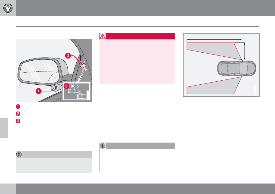
Blind Spot Information System (BLIS)*
06
162
*
Option/accessory, for more information, see Introduction.
Introduction
G020295
BLIS camera
Indicator light
BLIS symbol
The Blind Spot Information System (BLIS) is an
information system that indicates the presence
of another vehicle moving in the same direction
as your vehicle in the side-view mirror's "blind
area".
CAUTION
The BLIS system should only be repaired by
a trained and qualified Volvo service tech-
nician.
WARNING
•
BLIS is an information system, NOT a
warning or safety system.
•
BLIS does not eliminate the need for
you to visually confirm the conditions
around you, and the need for you to turn
your head and shoulders to make sure
that you can safely change lanes.
•
As the driver, you have full responsibility
for changing lanes in a safe manner.
The system is based on digital camera tech-
nology. The cameras (1) are located beneath
the side-view mirrors.
When one (or both) of the cameras have
detected a vehicle in the blind area (up to
approximately 10 ft. (3 meters) from the side of
your vehicle, and up to approximately 31 ft.
(9.5 meters) behind the side-view mirror), the
indicator light in the door panel (2) illuminates.
The light will glow continuously to alert the
driver of the vehicle in the blind area.
NOTE
The door panel indicator light illuminates on
the side of the vehicle where the system has
detected another vehicle. If your vehicle is
passed on both sides at the same time, both
lights will illuminate.
A
B
G020296
A = approx. 10 ft. (3 meters), B = approx. 31 ft.
(9.5 meters)
BLIS has an integrated function that alerts the
driver if a fault should occur with the system.
For example, if one or both of the system's
cameras are obscured, a message (see the
table on page 165) will appear in the informa-
tion display in the instrument panel. If this
occurs, clean the camera lenses. If necessary,
the system can be temporarily switched off (for
instructions see page 164).