Volvo 50-42LE transmission. Service manual - part 12
AUTOMATIC TRANSMISSION SERVICE GROUP
Technical Service Information
47
Copyright © 2004 ATSG
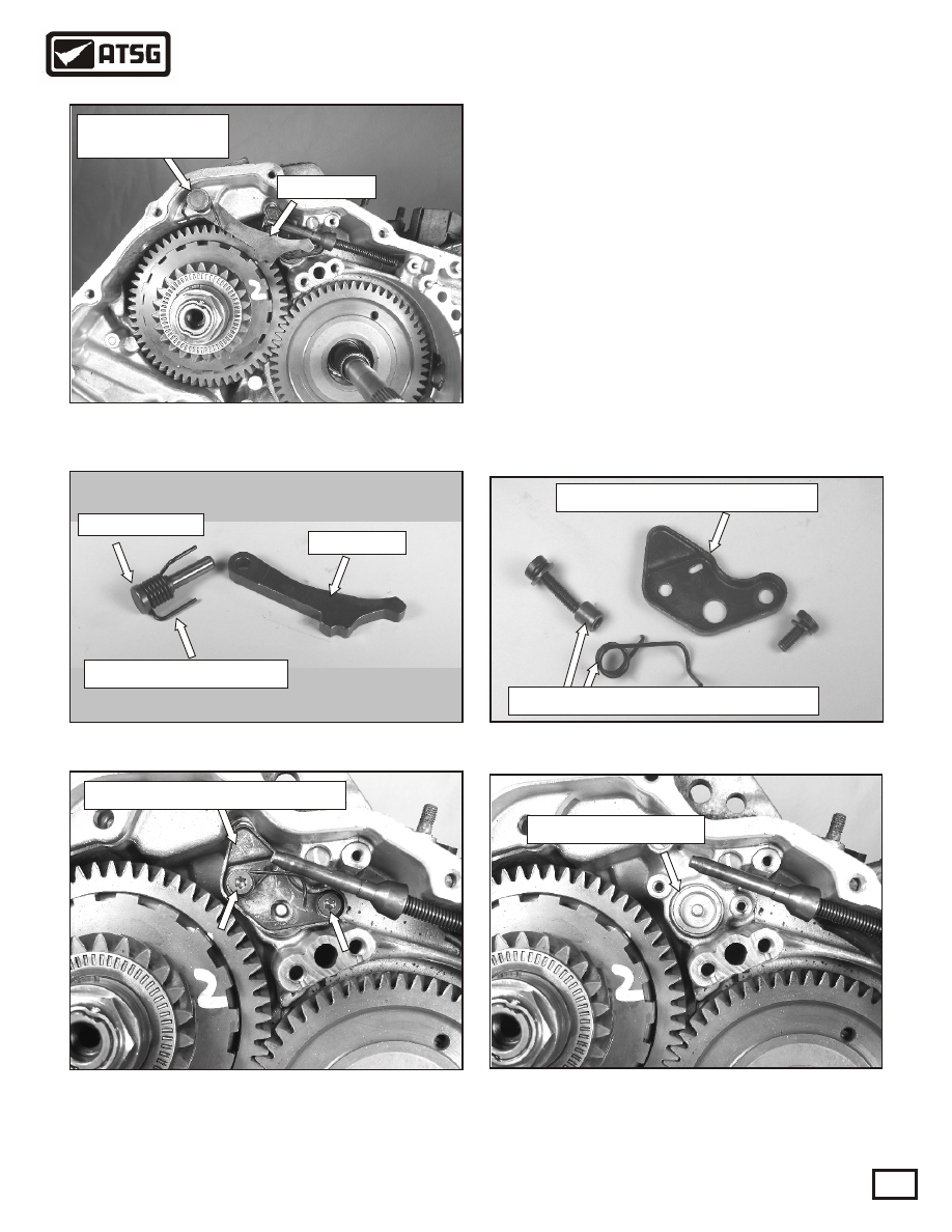
Figure 55
14. Remove the park pawl pin and return spring.
Remove the park pawl as shown in Figure 55.
Refer to Figure 56 to see this assembly
removed from the case.
15. Remove the two B4 accumulator retaining
plate bolts and plate, using a 30 torx bit, as
shown in Figure 57.
The bolt on the left anchors the sleeve and
parking rod return spring, as shown in the
close-up in Figure 58. Note: The bolt on the
left is 22mm long. The bolt on the right is
13.5mm long. CAUTION: B4 accumulator
is spring loaded in your direction.
16. Remove the B4 accumulator cap, as shown in
Figure 59.
TRANSMISSION DISASSEMBLY
CONTINUED
Continued on Page 48
REMOVED
Park pawl return spring
Park pawl
Park pawl pin
Figure 56
Pin in pic
Park pawl pin
and return spring
Park pawl
Figure 57
B4 accumulator retaining plate
B4 accumulator cap
Figure 59
B4 accumulator retaining plate
Parking rod return spring and sleeve
Figure 58