Volkswagen Golf / Golf GTI / Golf Variant. Service manual - part 721


  Index      Volkswagen     Volkswagen Golf / Golf GTI / Golf Variant - service and repair manual 2013 year


Search            copyright infringement  


Content   ..  719  720  721  722   ..


Volkswagen Golf / Golf GTI / Golf Variant. Service manual - part 721


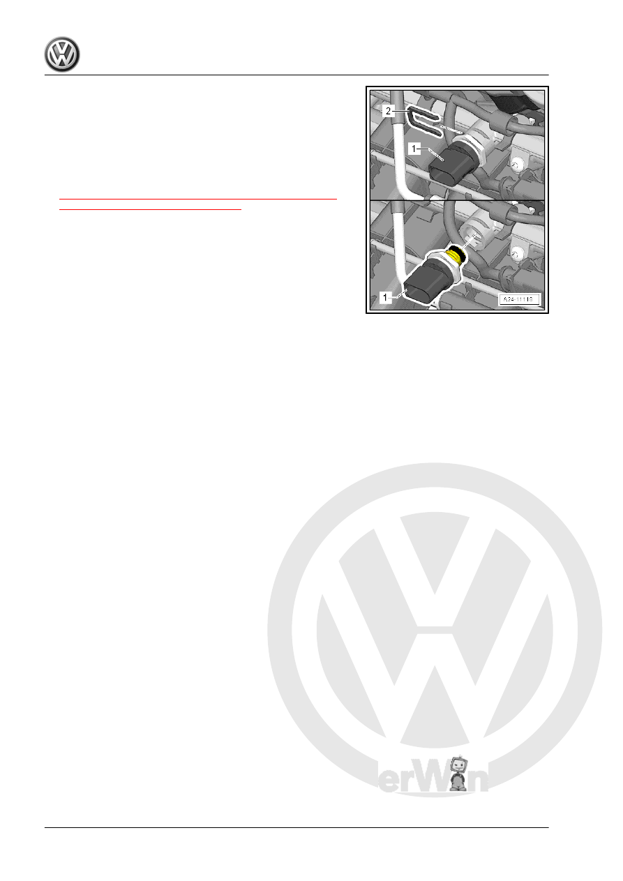
– Carefully slide the Low Fuel Pressure Sensor - G410- -1- all

the way into the fuel rail.

– To secure the Low Fuel Pressure Sensor - G410- , slide the

clip -2- into the groove.

– Connect the connector.
Tightening Specifications
♦ Refer to

⇒ “4.2.2 Overview - Intake Manifold Lower Section with Fuel

Rail, Multiport Fuel Injection”, page 302

 .

6

Engine Control Module

⇒ “6.1  Engine Control Module J623 , Removing and Installing”,

page 321

6.1

Engine Control Module - J623- , Remov‐

ing and Installing

⇒ “6.1.1  Engine Control Module J623 , Removing and Installing,

without Protective Housing”, page 321
⇒ “6.1.2  Engine Control Module J623 with Protective Housing,

Removing and Installing”, page 322

6.1.1

Engine Control Module - J623- , Remov‐

ing and Installing, without Protective

Housing

Special tools and workshop equipment required
♦ Vehicle Diagnostic Tester
Removing
– Turn on the ignition and select the following menu items on the

Vehicle Diagnostic Tester :

01 - Engine Electronics

Guided Functions

01 - Engine Control Module Replacing

– Turn off the ignition and remove the key.

Note

Touching the engine control module with the battery positive ter‐

minal damages the engine control module. For this reason the

battery must be disconnected before removing the engine control

module from its mount. Refer to ⇒  Electrical Equipment; Rep. Gr. 

27 ; Battery; Battery, Disconnecting and Connecting .

– Release the retainers in direction of -arrow A- and remove the

Engine Control Module - J623- in direction of -arrow B-.

– Unlock and disconnect the connectors from the Engine Con‐

trol Module - J623- .

Installing
Install in reverse order of removal. Note the following:
– Place the Engine Control Module - J623- in the bracket with

the lower edge forward in direction of -arrow A- and locked on

the upper edge.

• The ribs on the ECM must be engaged in the upper and lower

recesses on the bracket -B arrows-.

– Connect the battery. Refer to ⇒  Electrical Equipment; Rep.

Gr.  27 ; Battery; Battery, Disconnecting and Connecting .

Perform the Following after Installing a New ECM
– Turn on the ignition and select the following menu items on the

Vehicle Diagnostic Tester :

01 - Engine Electronics

Guided Functions

01 - Engine Control Module Replacing

6.1.2

Engine Control Module - J623- with Pro‐

tective Housing, Removing and Instal‐

ling

Special tools and workshop equipment required
♦ Wiring Harness Repair Set - Hot Air Blower - VAS1978/14A-

with nozzle attachment from the Wiring Harness Repair Set -

VAS1978B- .

♦ Mini-grinder, commercially available
♦ Vehicle Diagnostic Tester

Caution

This procedure contains mandatory replaceable parts. Refer

to component overview prior to starting procedure.

Mandatory Replacement Parts
♦ Bolts - Shear, Protective Housing
Removing
– Turn on the ignition and select the following menu items on the

Vehicle Diagnostic Tester :

01 - Engine Electronics

Guided Functions

01 - Engine Control Module Replacing

– Turn off the ignition and remove the key.

Note

Touching the engine control module with the battery positive ter‐

minal damages the engine control module. For this reason the

battery must be disconnected before removing the engine control

module from its mount. Refer to ⇒  Electrical Equipment; Rep. Gr. 

27 ; Battery; Battery, Disconnecting and Connecting .

Remove the shear bolts -arrows- to remove the protective hous‐

ing -1- as follows:

– Make a recess in the head of the shear bolt -1- for a screw‐

driver. Use a mini-grinder -2- to make the recess.

Note

The shear bolts were installed with a locking fluid. For this reason,

the threads must be heated with the heat gun to remove both

bolts.

– Adjust the settings on the hot air gun as shown. That means

the temperature potentiometer -2- set to maximum heat and

the two-stage airflow switch -3- set to level 3.

NOTICE

Risk of damaging the surrounding components using the hot air

gun. Overheating is possible.
– If necessary, cover the surrounding components.

– Warm the head of the shear bolt -1- for 20 to 30 seconds.


Content   ..  719  720  721  722   ..