Volkswagen Golf / Golf GTI / Golf Variant. Service manual - part 522
Grooved Ball Bearing Installation Location and Installing the
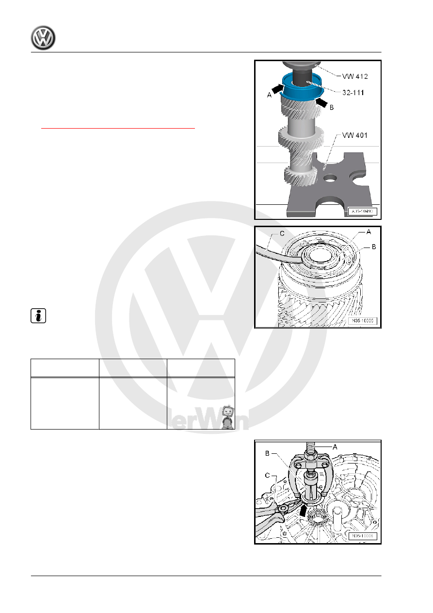
Grooved Ball Bearing
• Grooved ball bearing installed position: The groove for the
locking ring faces up -arrow A- and the collar -arrow B- must
face the 5th gear wheel.
– Then select the grooved ball bearing locking ring and install it
on the input shaft. Refer to
⇒ Fig. ““Selecting the Locking Ring”“ , page 160
Selecting the Locking Ring
– Insert a 1.86 mm locking ring -A- into groove in the input shaft
and press it upward.
– Measure the gap between the grooved ball bearing -B- and
the installed locking ring -A- with a feeler gauge -C-.
– Remove the locking ring used for the measurement.
– Select the locking ring according to the Table.
Note
For the correct locking rings. Refer to the Parts Catalog.
The following circlips are available:
Measured Value
(mm)
Circlip Ring Thick‐
ness (mm)
Axial Play (mm)
0.01 to 0.05
1.86
0.01 to 0.05
0.05 to 0.07
1.89
0.01 to 0.05
0.07 to 0.10
1.92
0.01 to 0.05
0.10 to 0.13
1.95
0.01 to 0.05
0.13 to 0.16
1.98
0.01 to 0.05
Removing the Cylindrical Roller Bearing from the Clutch Housing
– Compress the cylindrical roller bearing locking ring -arrow-
with pliers -C- and remove it.
A - Counter Support , for example, -22/2-
B - Internal Puller 30 to 37 mm , for example, -21/5-