Volkswagen Golf / Golf GTI / Golf Variant. Service manual - part 164
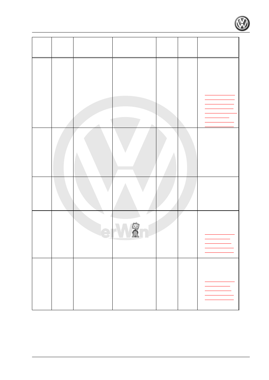
DTC /
Descrip‐
tion
Monitor
Strategy
Descrip‐
tion
Malfunction Crite‐
ria and Threshold
Value
Secondary Parame‐
ters with Enable
Conditions
Monitor‐
ing Time
Length
MIL Il‐
lum.
Component Diag‐
nostic Procedure
P2027
EVAP
Fuel Va‐
por
Temper‐
ature
Sensor
Circuit
High
Voltage
Smart
Tempera‐
ture Sen‐
sor Short
To Bat‐
tery Volt‐
age
• NVLD output
temperature >
160.0 – 200.0°
C
• Or
• NVLD output
current driver
stage internal
value
• Case 1:
• Ignition on
• Case 2:
• Ignition off (dur‐
ing ECM keep
alive-time)
• 0.5 s
• Con‐
tinu‐
ous
• 2
DCY
– Check the Fuel
Tank Leak De‐
tection Control
Module - J909- /
Fuel Tank Pres‐
sure Sensor -
G400- . Refer to
.
P2067
Fuel
Level
Sensor
"B" Cir‐
cuit Low
COM:
Fuel Lev‐
el (FL)
Sensor 2
commu‐
nication
with IPC
• Instrument
cluster module
signal: short to
ground failure
• Instrument
cluster module
signal: signal
range check
failure
• 0.5 s
• Con‐
tinu‐
ous
• 2
DCY
– Check the Fuel
Level Sensor -
G- . Refer to ap‐
propriate repair
manual.
P2068
Fuel
Level
Sensor
"B" Cir‐
cuit High
COM:
Fuel Lev‐
el (FL)
Sensor 2
commu‐
nication
with IPC
• Instrument
cluster module
signal: short to
battery / open
circuit failure
• 0.5 s
• Con‐
tinu‐
ous
• 2
DCY
– Check the Fuel
Level Sensor -
G- . Refer to ap‐
propriate repair
manual.
P2088
"A"
Cam‐
shaft
Position
Actuator
Control
Circuit
Low
Bank 1
VVT Ac‐
tuator In‐
take
Short To
Ground
• Output voltage
(hardware val‐
ues) < 1.92 –
2.21 V
• Actuator com‐
manded off
• 2.0 s
• Con‐
tinu‐
ous
• 2
DCY
– Check the Cam‐
shaft Adjust‐
ment Valve 1 -
N205- . Refer to
.
P2089
"A"
Cam‐
shaft
Position
Actuator
Control
Circuit
High
Bank 1
VVT Ac‐
tuator In‐
take
Short To
Battery
Plus
• Power stage
temperature >
160 – 200° C
• Or
• Output current
(hardware val‐
ues) driver
stage internal
value
• Actuator com‐
manded on
• 2.0 s
• Con‐
tinu‐
ous
• 2
DCY
– Check the Cam‐
shaft Adjust‐
ment Valve 1 -
N205- . Refer to
.
GTI 2014 ➤
Generic Scan Tool - Edition 04.2015
3. Diagnosis and Testing
329