Volkswagen Golf / Golf GTI / Jetta. Service manual - part 390
01-305
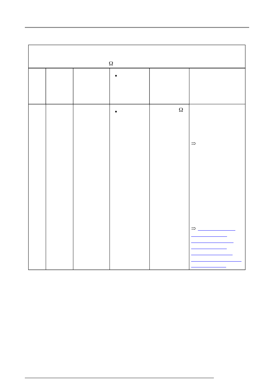
Switch to measuring range:
Resistance measurement (2 k
)
Test
step
V.A.G
1598
sockets
Item tested
Test
conditions
- Additional
operations
Specification Measures for
deviations from
specification
8
37 + 36 Resistance
of left rear
ABS wheel
speed
sensor -G46-
Ignition
switched
off
1.0 - 1.3 k
Electrical Wiring
Diagrams,
Troubleshooting &
Component
Locations binder
If no malfunction can
be located in the
wiring:
Repair Manual,
Brake System,
Repair Group 45;
Removing and
installing parts of
ABS system on front
and rear axles
- Check wiring using
wiring diagram
- Wiggle wiring
during test
- Replace left rear
ABS wheel speed
sensor -G46-
Electrical check of Mark 60