Volkswagen Golf / Golf GTI / Jetta. Service manual - part 254
28-36
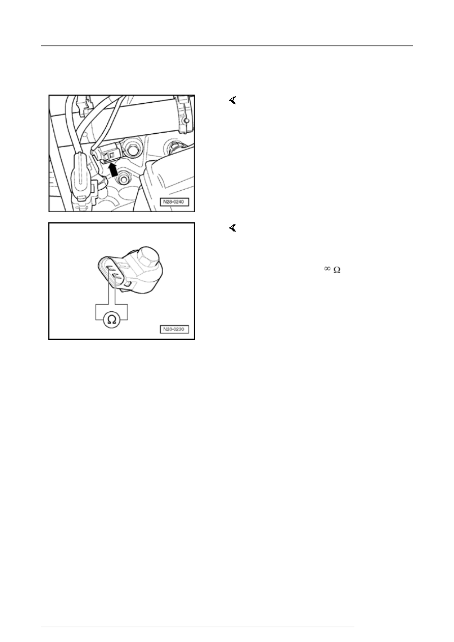
Knock Sensor (KS) 2 -G66-
- Disconnect 2-pin connector from
Knock Sensor (KS) 2 -G66-
(arrow)(on intake side of cylinder
head).
- Measure resistance between
terminals 1 and 2 at connector to
Knock Sensor (KS) 2 -G66-.
Specification:
Ignition system, servicing