Volkswagen Golf / Golf GTI / Jetta. Service manual - part 251
28-24
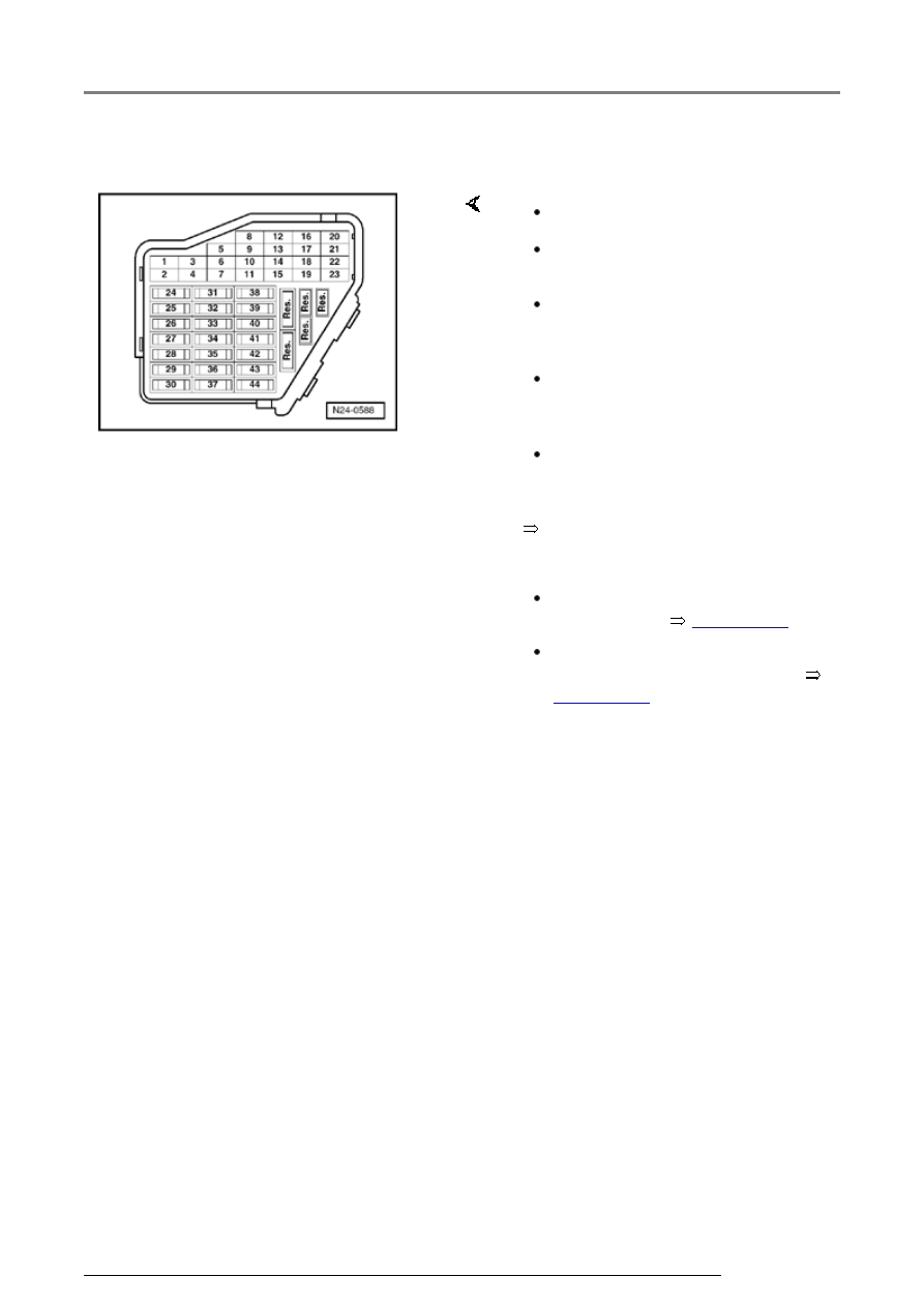
Test requirements
Electrical Wiring Diagrams,
Electrical troubleshooting and
Component locations
The fuses must be OK.
The battery voltage must be at
least 11.5 V.
All electrical accessories, e.g.
lights and rear window defroster
must be switched off.
If the vehicle is equipped with air
conditioning, this must be
switched off.
Motronic Engine Control Module
(ECM) Power Supply Relay -
J271- must be OK., checking:
Engine speed sensor must be
OK, checking
Page 24-93
.
Camshaft Position (CMP)
Sensor must be OK, checking
Page 28-16
.
Ignition system, servicing