Volkswagen Golf / Golf GTI / Jetta. Service manual - part 165


  Index      Volkswagen     Volkswagen Golf / Golf GTI / Jetta - service and repair manual 1999-2005 year


Search            copyright infringement  


Content   ..  163  164  165  166   ..


Volkswagen Golf / Golf GTI / Jetta. Service manual - part 165


01-202


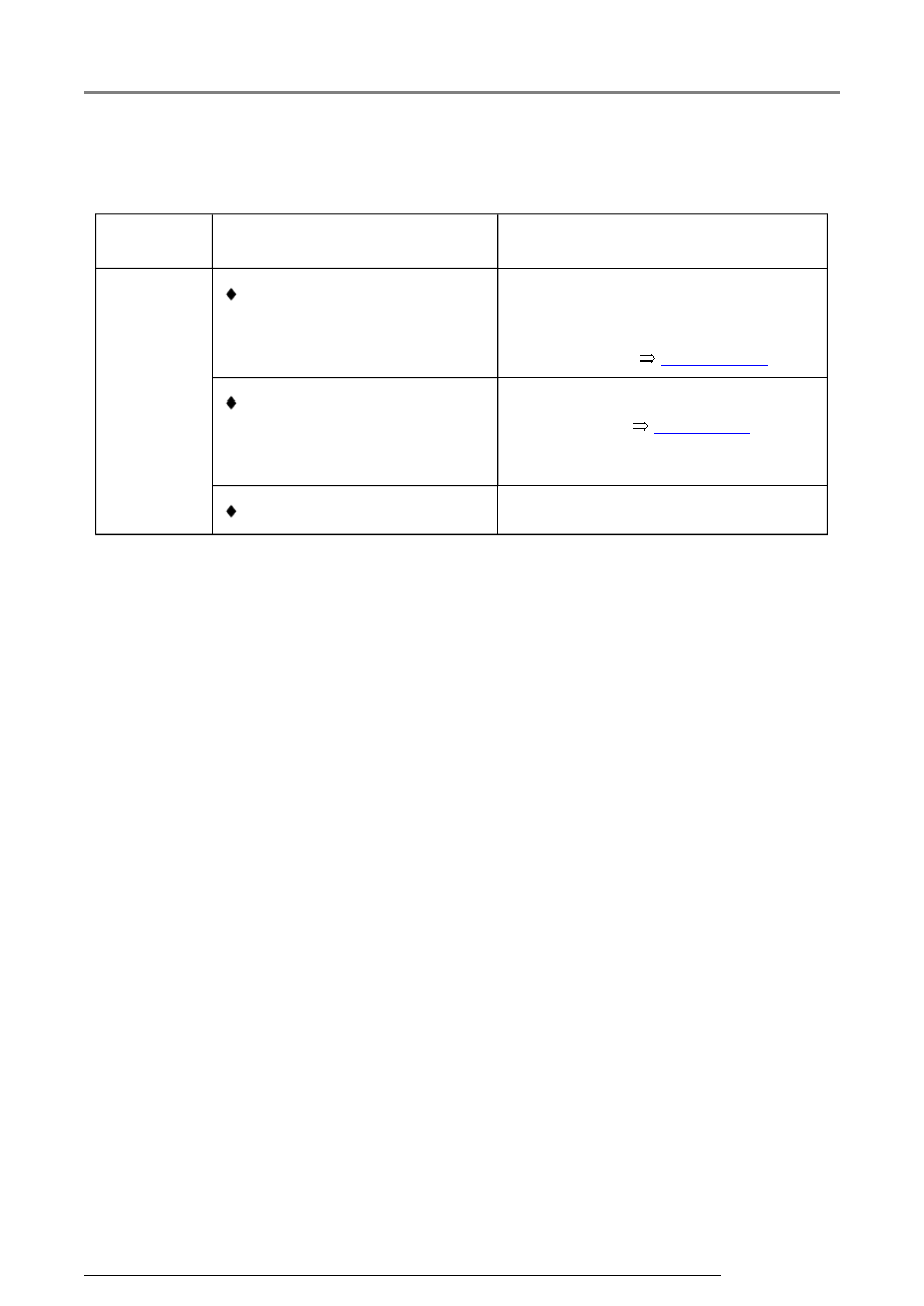
Evaluating display group 10, display zone 3 - Throttle valve angle, Angle sensor -
1- for throttle drive 
 

Appears on 

display  

Possible cause  

Corrective action  

Greater 

than 

specified  

 Motronic Engine Control 

Module (ECM) -J220- not 
adapted to Throttle Valve 
Control Module -J338- 

- Erase learned values and adapt 
Motronic Engine Control Module 
(ECM) -J220- to Throttle Valve 
Control Module 


Page 24-182


 Faulty Angle sensor -1- for 

throttle drive -G187- in 
Throttle Valve Control 
Module -J338- 

- Check Throttle Valve Control 
Module -J338- 


Page 24-59


 Throttle valve sticking 

- Repair cause 

Measured value (data) blocks

01-203


Display group 14 - Ignition - Misfire detection  

 While driving 

Read measured value 
block 14  


 Indicated on 

display  


xxxx rpm   xxx.x %   xxx   Text     


 Display zones  

Specification  

Evaluation  


Misfire detection  

(inactive, 
activated)  


Activated  


---  


Misfire total  

0  


Page 01-

204


Engine load  

12.0...100.0 %  

---  


Engine speed  

640...6500 

rpm  

---  

Note on display zone 3:  

The total number of detected misfires is displayed here. No distinction is made over what 
period of time the misfire was detected. Therefore check the misfire detection during a 
road test 


Page 28-40

 . 

Measured value (data) blocks

01-204


Evaluating display group 14, display zone 3 - Total number of misfires   

Appears on 

display  

Possible cause  

Corrective action  

Greater than 

specified  

 Spark connector faulty 

- Check spark connectors 


Page 28-

15


 Ignition coil faulty 

 Ignition coil final output 

stage faulty 

- Check ignition coils with final output 
stage 


Page 28-23


 Fuel injector faulty 

- Check fuel injectors 


Page 24-97


 Inlet camshaft adjuster 

sticking/faulty 

 Exhaust camshaft adjuster 

sticking/faulty 

 Inlet Valve -1- for camshaft 

adjustment -N205- faulty 

 Exhaust Valve -1- for 

camshaft adjustment -
N318- faulty 


Repair Manual, 2.8 Liter VR6 4V 

Engine Mechanical, Engine Code(s): 
BDF; Repair Group 15


- Check camshaft timing adjustment 
valve 


Page 01-100

 , Output 

Diagnosis Test Mode (DTM) 

- Check camshaft timing adjustment: 


 Timing incorrectly set 


Repair Manual, 2.8 Liter VR6 4V 

Engine Mechanical, Engine Code(s): 
BDF; Repair Group 15


- Check timing: 

Measured value (data) blocks

01-205


Display group 15 - Ignition - Misfire detection cyl. 1 to cyl. 3   

 While driving 

Read measured value 
block 15  


 Indicated on 

display  


xxx  

xxx  

xxx  

Text     


 Display zones  

Specification  

Evaluation  


Misfire detection  

(inactive, 
activated)  


Activated  


---  


Ignition misfire cyl. 3  

0  


Page 01-

207


Ignition misfire cyl. 2  

0  


Page 01-

207


Ignition misfire cyl. 1  

0  


Page 01-

207


Measured value (data) blocks


Content   ..  163  164  165  166   ..