Volkswagen Golf / Golf GTI / Jetta. Service manual - part 132


  Index      Volkswagen     Volkswagen Golf / Golf GTI / Jetta - service and repair manual 1999-2005 year


Search            copyright infringement  


Content   ..  130  131  132  133   ..


Volkswagen Golf / Golf GTI / Jetta. Service manual - part 132


01-107


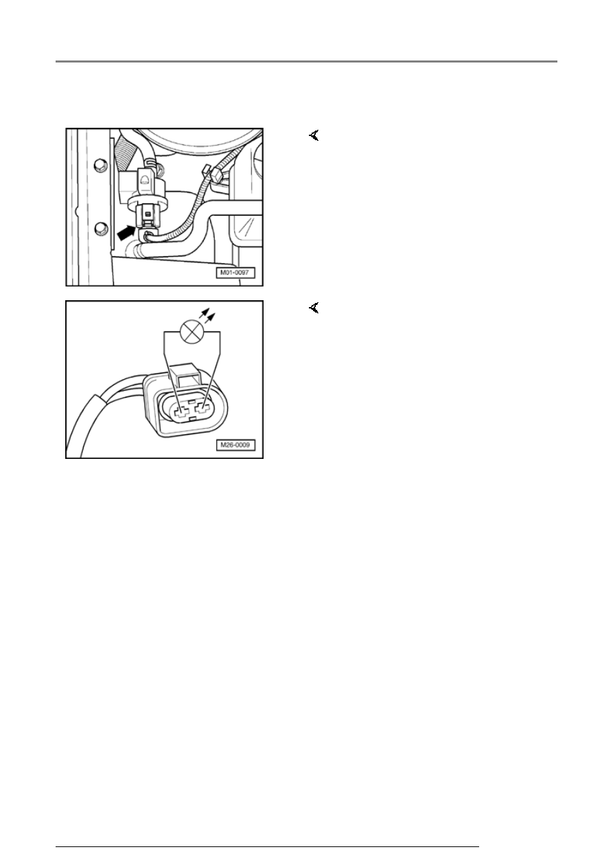
If the solenoid valve does not click:  


-  Disconnect 2-pin connector from 

Evaporative Emission (EVAP) 
Canister Purge Regulator Valve -
N80- (arrow). 


LED flashes:  

-  Connect LED test light VAG 1527 

to disconnected connector using 
adapter cables from VAG 1594. 

   LED must flash (bright/darker) 

-  Press -C- button to abort output 

Diagnosis Test Mode (DTM). 

Output Diagnosis Test Mode (DTM)

01-108


Output Diagnosis Test Mode was aborted

     Indicated on display:  

LED does not flash:  

-  Switch off ignition. 

-  Replace Evaporative Emission 

(EVAP) Canister Purge 
RegulatorValve -N80-. 

-  Check DTC memory, repair 

Diagnostic Trouble Codes (DTCs) 
if necessary and then erase DTC 
memory 


Page 01-23

 , DTC 

memory, checking and erasing. 

-  Read readiness code 


Page 01-

146

 . If the DTC memory has 

been erased or the Motronic 
Engine Control Module (ECM) -
J220- was disconnected from 
battery (B+) positive, the 
readiness code must be 
generated again 


Page 01-149

 . 

-  Press -C- button to abort output 

Diagnosis Test Mode (DTM). 

Output Diagnosis Test Mode was aborted

     Indicated on display:  


Repair Manual, Electrical 

Equipment; Repair Group 92


-  Switch off ignition. 

-  Remove wiper arms and cowl 

panel: 

Output Diagnosis Test Mode (DTM)

01-109


-  Connect test box VAG 1598/31 to 

control module wiring harness. 
Engine Control Module (ECM) -
J220- remains disconnected. 


If no wiring malfunction is found:  

-  Check wire for open circuit 

between test box socket 64 and 
2-pin connector terminal 2 
referring to Electrical Wiring 
Diagrams. 

   Wire resistance: max. 1.5 


-  Additionally check wire for short 

to battery positive and Ground 
(GND). 

   Specification: 


-  Check wire for open circuit 

between 2-pin connector terminal 
1 and Fuel Pump (FP) relay -J17- 
referring to Electrical Wiring 
Diagrams. 

   Wire resistance: max. 1.5 


-  Replace Motronic Engine Control 

Module (ECM) -J220- 


Page 24-

173

 . 

Output Diagnosis Test Mode (DTM)

01-110


-  Check DTC memory, repair Diagnostic Trouble 

Codes (DTCs) if necessary and then erase DTC 
memory 


Page 01-23

 , DTC memory, checking 

and erasing. 


-  Erase learned values and adapt Motronic 

Engine Control Module (ECM) -J220- again 


Page 24-182

 . 


-  Read readiness code 


Page 01-146

 . If the 

DTC memory has been erased or the Motronic 
Engine Control Module (ECM) -J220- was 
disconnected from battery (B+) positive, the 
readiness code must be generated again 


Page 01-149

 . 


2. Activating Secondary Air Injection (AIR) 
Solenoid Valve -N112-: 


-  Press 

 button. 

Output Diagnosis Test Mode (DTM) 

Secondary Air Injection Solenoid Valve

     Indicated on display:  

   The Secondary Air Injection (AIR) Solenoid 

Valve must click, until the next final control 
element is activated by pressing 

button. 

Output Diagnosis Test Mode (DTM)


Content   ..  130  131  132  133   ..