Volkswagen Golf / Golf GTI / Jetta. Service manual - part 48


  Index      Volkswagen     Volkswagen Golf / Golf GTI / Jetta - service and repair manual 1999-2005 year


Search            copyright infringement  


Content   ..  46  47  48  49   ..


Volkswagen Golf / Golf GTI / Jetta. Service manual - part 48


15-81


Note:  

When the cylinder head is installed 
the holes in the cylinder head gasket 
are only half visible.
 

The rest of the assembly is basically 
in reverse order to the disassembling 
sequence.  

Note:  

Ensure that the O-ring for sealing the 
oil channel and the seal in the cover 
are installed.
 

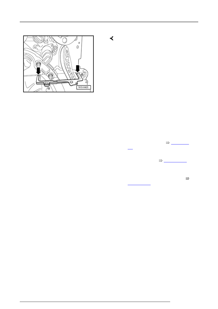
-  Remove old sealing compound 

from 3 mm holes in cylinder head 
gasket (arrows). 

-  Adjust valve timing 


Page 15-

39

 . 

-  Install cylinder head cover and 

intake manifold 


Page 15-16

 , 

Removing and installing cylinder 
head 

-  Check camshaft adjustments 


Page 15-82

 . 

Valve gear, servicing

15-82


Camshaft adjustment, checking 


   Function  


   The camshaft timing adjustment is dependent 

upon load and speed. Oil pressure is directed to 
the camshaft timing adjuster (mechanical 
adjustment unit) by the camshaft timing 
adjustment solenoid valve and the camshaft 
adjuster then adjusts the camshaft.  


   Special tools and equipment  


 V.A.G 1551 Scan Tool (or vehicle system tester 

V.A.G 1552) with cable V.A.G 1551/3 


   Note:  


   All functions which could previously be 

performed with V.A.G 1551/1552 can also be 
performed with the new tester VAS 5051.
 

Valve gear, servicing

15-83


Test conditions  


Repair Manual, 2.8 Liter VR6 4V 

Fuel Injection & Ignition, Engine 
Code(s): BDF, Repair Group 01


Checking activation  


Repair Manual, 2.8 Liter VR6 4V 

Fuel Injection & Ignition, Engine 
Code(s): BDF, Repair Group 01


 Fuses must be OK. 

 Battery voltage must be at least 

11.5 V. 

 All electrical consumers, e.g. 

lights and rear window defroster 
must be switched off. 

 If the vehicle is equipped with air 

conditioning, this must be 
switched off. 

 Selector lever must be in 

position "P" or "N" on vehicles 
with an automatic transmission. 

 Engine oil level OK, checking 


Page 17-8

 , Fig. 2 

 No DTCs may be stored in the 

DTC memory: 

-  Check Valve -1- for camshaft 

adjustment -N205- and Camshaft 
adjuster valve 1 (exhaust) -N318- 
via output Diagnostic Test Mode 
(DTM): 

Valve gear, servicing

15-84


If activation is OK.:  


Checking function of camshaft timing 
adjuster 


Test conditions  


 Coolant temperature must be at least 85 

C,

display group 1, display zone 2. 


Test sequence  


-  Connect V.A.G 1551 Scan Tool (or V.A.G 1552). 

Start engine and select "Address word" 01 of 
engine control module. Connect Scan Tool and 
select engine control module: 


Repair Manual, 2.8 Liter VR6 4V Fuel Injection 

& Ignition, Engine Code(s): BDF, Repair Group 
01


Rapid data transfer 

HELP

Select function XX

     Indicated on display  

-  Press keys 0 and 4 for function "Initiate basic 

setting" and confirm entry with Q key. 

Basic setting

Input display group number XXX

     Indicated on display  

-  Press keys 0, 0 and 1 for "Display group number 

1" and confirm entry with Q key. 

Valve gear, servicing


Content   ..  46  47  48  49   ..