Volkswagen Golf / Golf GTI / Jetta. Service manual - part 35
15-35
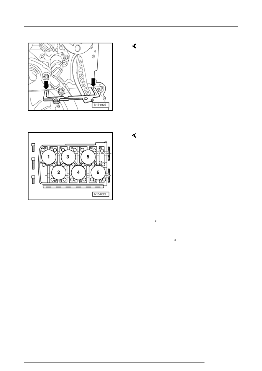
Note:
When the cylinder head is installed
the holes in the cylinder head gasket
are only half visible.
- Fill 3 mm holes in cylinder head
gasket with sealing compound
AMV 188 001 02.
- Install cylinder head, insert new
cylinder head bolts and tighten by
hand.
Note:
The longer cylinder head bolts must
be inserted in the middle holes of the
cylinder head.
- Tighten cylinder head bolts in
tightening sequence as follows:
- Pretighten all bolts to 30 Nm.
- Then tighten all bolts to 50 Nm.
- Then tighten all bolts
1
/
4
turn (90
) further with a rigid wrench.
- Then tighten all bolts again
1
/
4
turn (90 ) further.
Cylinder head, servicing