Volkswagen Golf / Golf GTI / Jetta. Service manual - part 18
13-29
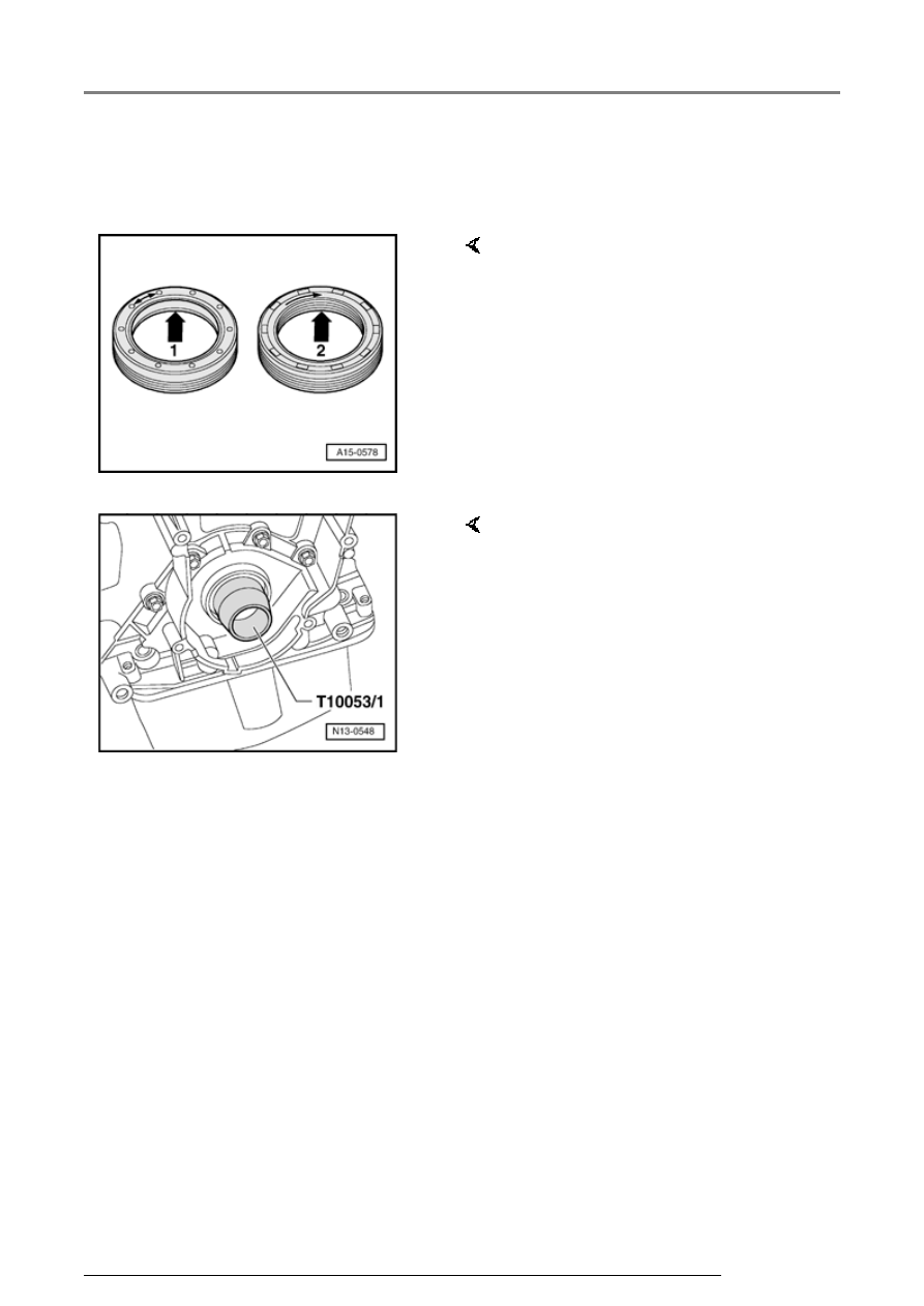
Installing
Note:
A PTFE seal (Teflon) -2- is gradually
being introduced instead of the inner
coil spring type seal-1-. This has a
wider sealing lip. PTFE seals are
fitted free of oil and grease. When a
PTFE seal is installed, then only
such a seal may be installed as a
replacement part!
- Before installing, remove oil
remains from crankshaft journal
with a clean cloth.
- Install guide sleeve T10053/1
onto crankshaft journal and
carefully slide seal onto guide
sleeve
Sealing flanges and dual-mass flywheel, removing and installing