Volkswagen New Beetle. Manual - part 1880


  Index      Volkswagen     Volkswagen New Beetle 1998-2008 year - service repair manual


Search            


Content   ..  1878  1879  1880  1881   ..


Volkswagen New Beetle. Manual - part 1880


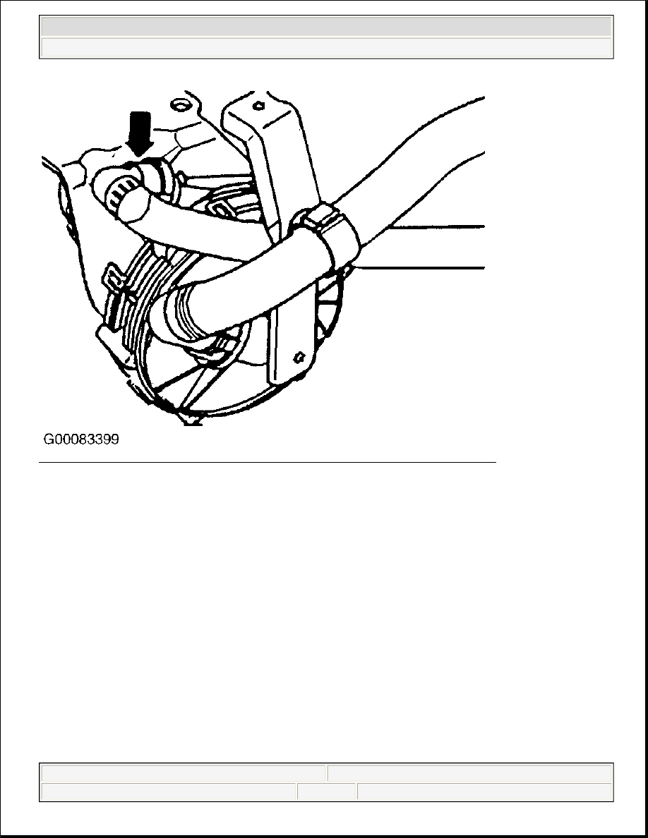
Fig. 51: Locating Secondary Air Pump Motor (V101) Air Pressure Outlet Connector 
Courtesy of VOLKSWAGEN UNITED STATES, INC.


2003 Volkswagen New Beetle GLS 

2002-2003 ENGINE PERFORMANCE Self-Diagnostics - 1.8L Turbo


Helpmelearn Repair Manuals 


Wednesday, December 14, 2005 8:44:41 AM

Page 142 

© 2004 Mitchell Repair Information Company, LLC. 

Fig. 52: Identifying Secondary Air System Components & Hoses 
Courtesy of VOLKSWAGEN UNITED STATES, INC. 

DTC P0412/16796, DTC P0413/16797 & DTC P0414/16798 

Code Definition 

z

DTC P0412/16796: Secondary Air Injection Valve (N112) - Electrical Circuit Malfunction  

z

DTC P0413/16797: Secondary Air Injection Valve (N112) - Open Circuit  

z

DTC P0414/16798: Secondary Air Injection Valve (N112) - Short Circuit 

NOTE:

If a test ends with ECM replacement. Before replacing ECM be certain that, all 
wiring, power and ground supplies are okay. See ENGINE PERFORMANCE in 
SYSTEM WIRING DIAGRAMS article in ELECTRICAL and ECM GROUND & 
VOLTAGE SUPPLY . 


2003 Volkswagen New Beetle GLS 

2002-2003 ENGINE PERFORMANCE Self-Diagnostics - 1.8L Turbo


Helpmelearn Repair Manuals 


Wednesday, December 14, 2005 8:44:41 AM

Page 143 

© 2004 Mitchell Repair Information Company, LLC. 

Test Requirements 

Ensure all fuses are okay, battery voltage is at least 11.5 volts, all electrical accessories are off, A/C is off. 
Ensure engine is mechanically sound.  

Test Procedure 

Check hoses and components of Secondary Air Injection System, for damage, loose fit and improper 
installation, check vacuum hoses for Secondary Air Injection System, repair as necessary, erase DTC memory. 
Verify repair. Test is complete. Perform ECM relearn procedure. See TEST DRIVE RELEARN 
PROCEDURE 
.  

1. Check vacuum hoses for Secondary Air Injection System, repair as necessary, go to next step.  

2. Using scan tool, check Secondary Air Injection Valve (N112). See OUTPUT DIAGNOSTIC TEST 

MODE . Secondary Air Injection Valve should audibly click. If Secondary Air Injection Valve clicks, 
erase DTC memory. Perform ECM relearn procedure. See TEST DRIVE RELEARN PROCEDURE 
If DTC does not reset on test drive. Test is complete. If Secondary Air Injection Pump Relay does not 
click, go to step, 4 . If DTC(s) resets, go to next step.  

3. Disconnect vacuum hose from Combi-Valve. See Fig. 53 . Start engine and idle, vacuum should be 

present when Secondary Air Pump Motor (V101) is running. If no vacuum is present, go to next step. If 
vacuum is present, erase DTC memory. Test is complete. Perform ECM relearn procedure. See TEST 
DRIVE RELEARN PROCEDURE 
.  

4. Disconnect harness connector from Secondary Air Injection Valve (N112). Connect LED test light to 

secondary air injection valve harness connector, start engine, LED test light should illuminate. If test light 
does not illuminate, go to next step. If test light illuminates, replace faulty Secondary Air Injection Valve 
(N112). Erase DTC memory. Verify repair. Test is complete. Perform ECM relearn procedure. See TEST 
DRIVE RELEARN PROCEDURE 
.  

5. Using DVOM check resistance of Secondary Air Injection Valve (N112) wiring. See appropriate 

WIRING DIAGRAM under ENGINE PERFORMANCE in SYSTEM WIRING DIAGRAMS. Resistance 
should be a maximum of 1.5 ohms for each reading. Check wiring for short circuit to one another in 
Secondary Air Injection Valve (N112) harness connector. Repair as necessary. Erase DTC memory. 
Verify repair. Test is complete. Perform ECM relearn procedure. See TEST DRIVE RELEARN 
PROCEDURE 
. If all wiring is okay, replace faulty ECM. See ENGINE CONTROL MODULE 
REMOVAL & INSTALLATION 
. Erase DTC memory. Verify repair. Test is complete. Perform ECM 
relearn procedure. See TEST DRIVE RELEARN PROCEDURE 

NOTE:

Output Diagnostic Test Mode is used when using Scan Tools VAG 1551/1552 or 
VAS 5051/5052, always continue with output diagnostic test mode until last 
component in output diagnostic test mode test sequence has been checked. If 
you are not using Scan Tools VAG 1551/1552 or VAS 5051/5052 follow scan tool 
manufacturer's instructions. 

NOTE:

Secondary air system is activated by ECM and blows air into exhaust pipe 
upstream of catalytic converter for 100 seconds during a cold start, 41-91°F (5-
33°C). Engine must be cold to perform following test procedure. 


2003 Volkswagen New Beetle GLS 

2002-2003 ENGINE PERFORMANCE Self-Diagnostics - 1.8L Turbo


Helpmelearn Repair Manuals 


Wednesday, December 14, 2005 8:44:41 AM

Page 144 

© 2004 Mitchell Repair Information Company, LLC. 

Fig. 53: Locating Secondary Air Injection Valve/Combi-Valve Vacuum Hose (GTI & Jetta) 
Courtesy of VOLKSWAGEN UNITED STATES, INC. 

DTC P0418/16802: SECONDARY AIR PUMP RELAY (J299) - MALFUNCTION 

Test Requirements 

Ensure all fuses are okay, battery voltage is at least 11.5 volts, all electrical accessories are off, A/C is off. 
Ensure engine is mechanically sound.  

Test Procedure 

1. Using scan tool, check Secondary Air Injection Pump Relay (J299). See OUTPUT DIAGNOSTIC 

TEST MODE . Secondary Air Injection Pump Relay should audibly click. Secondary Air Injection 

NOTE:

Output Diagnostic Test Mode is used when using Scan Tools VAG 1551/1552 or 
VAS 5051/5052, always continue with output diagnostic test mode until last 
component in output diagnostic test mode test sequence has been checked. If 
you are not using Scan Tools VAG 1551/1552 or VAS 5051/5052 follow scan tool 
manufacturer's instructions. 


2003 Volkswagen New Beetle GLS 

2002-2003 ENGINE PERFORMANCE Self-Diagnostics - 1.8L Turbo


Helpmelearn Repair Manuals 


Wednesday, December 14, 2005 8:44:41 AM

Page 145 

© 2004 Mitchell Repair Information Company, LLC. 


Content   ..  1878  1879  1880  1881   ..