Volkswagen New Beetle. Manual - part 1871


  Index      Volkswagen     Volkswagen New Beetle 1998-2008 year - service repair manual


Search            


Content   ..  1869  1870  1871  1872   ..


Volkswagen New Beetle. Manual - part 1871


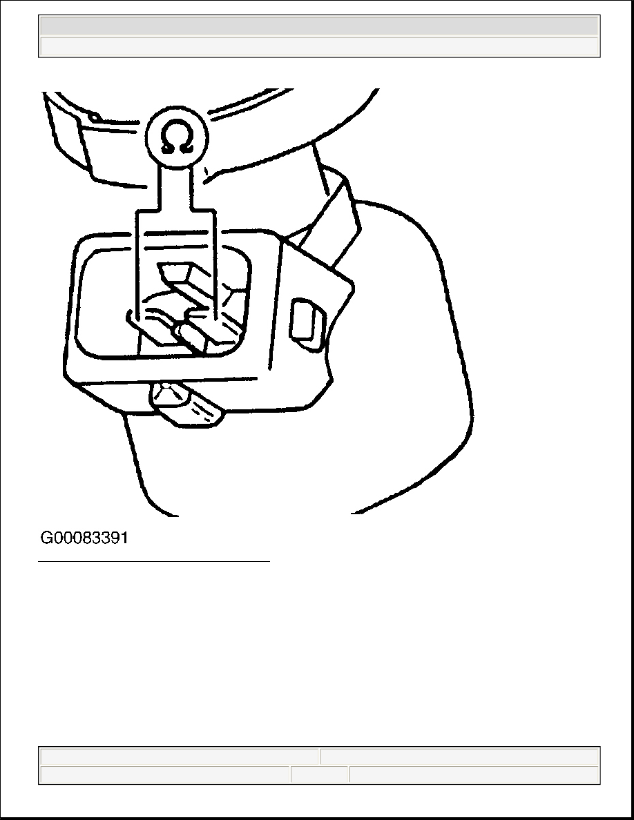
Fig. 35: Identifying Fuel Injector Terminals 
Courtesy of VOLKSWAGEN UNITED STATES, INC.


2003 Volkswagen New Beetle GLS 

2002-2003 ENGINE PERFORMANCE Self-Diagnostics - 1.8L Turbo


Helpmelearn Repair Manuals 


Wednesday, December 14, 2005 8:44:37 AM

Page 106 

© 2004 Mitchell Repair Information Company, LLC. 

Fig. 36: Identifying Fuel Injector Harness Connector Terminals (Beetle, GTI & Jetta) 
Courtesy of VOLKSWAGEN UNITED STATES, INC. 

DTC P0219/16603: MAXIMUM ENGINE RPM EXCEEDED 

Test Requirements 

Ensure all fuses are okay, battery voltage is at least 11.5 volts, all electrical accessories are off, A/C is off. 
Engine is mechanically sound. Ensure engine coolant temperature is at least 176°F (80°C).  

Test Procedure 

Connect scan tool. See RETRIEVING DIAGNOSTIC TROUBLE CODES . Turn ignition on, engine off. 
Check and record DTCs. Erase DTCs. Repair mechanical damage.  

DTC P0221/16605, DTC P0222/16606 & DTC P0223/16607 


2003 Volkswagen New Beetle GLS 

2002-2003 ENGINE PERFORMANCE Self-Diagnostics - 1.8L Turbo


Helpmelearn Repair Manuals 


Wednesday, December 14, 2005 8:44:37 AM

Page 107 

© 2004 Mitchell Repair Information Company, LLC. 

Code Definition 

z

DTC P0221/16605: Angle Sensor 2 (G188) For Throttle Valve Drive - Implausible Signal  

z

DTC P0222/16606: Angle Sensor 2 (G188) For Throttle Valve Drive - Signal Too Low  

z

DTC P0223/16607: Angle Sensor 2 (G188) For Throttle Valve Drive - Signal Too High  

Circuit/Component Description 

Throttle Valve Control Module (TVCM - J338) is located on throttle body. Throttle valve drive angle sensors 
and are located in TVCM (J338). ECM monitors throttle valve drive angle sensors for throttle valve position. 
ECM calculates throttle position based on percentage values sent by throttle valve drive angle sensors. Throttle 
valve drive angle sensors run in opposite directions of each other. Throttle Valve Drive Angle sensor No. 1 
(G187) displays throttle positions from 3-93 percent. Throttle Valve Drive Angle sensor No. 2 (G188) displays 
throttle positions from 97-3 percent. Throttle Valve Drive Angle sensor No. 1 (G187) ranges from 3-93 percent 
(0.15-4.65 volts), the larger the throttle opening the higher the percentage (voltage) reading. Throttle Valve 
Drive Angle sensor No. 2 (G188) ranges from 97-3 percent (4.90-0.15 volts), the larger the throttle opening the 
smaller the percentage (voltage) reading. When the engine is running (under load) the ECM can operate throttle 
valve independently of driver input.  

Test Requirements 

Ensure throttle valve is not damaged or dirty. Ensure all fuses are okay, battery voltage is at least 11.5 volts and 
fuel pump relay is okay. Ensure all electrical accessories are off and A/C is off. Ensure engine is mechanically 
sound. Ensure no intake or exhaust system leaks exist. Ensure engine coolant temperature is at least 176°F (80°
C).  

Test Procedure 

1.  

Turn ignition off. Disconnect TVCM (J338) 6-pin harness connector. Using DVOM check resistance 
between terminals No. 3 and 5 on TVCM. See Fig. 20 . Specification is one to 5 ohms. If resistance is 
okay, go to next step. If resistance is not okay, replace faulty TVCM. Erase DTC memory. Verify repair. 
Test is complete. Adapt TVCM (J338) to ECM (J220), see THROTTLE VALVE CONTROL 
MODULE (J338) 
. For vehicles with A/T, adapt TVCM (J338) to Transmission Control Module (J217), 

NOTE:

If a test ends with ECM replacement. Before replacing ECM be certain that, all 
wiring, power and ground supplies are okay. See ENGINE PERFORMANCE in 
SYSTEM WIRING DIAGRAMS article in ELECTRICAL and ECM GROUND & 
VOLTAGE SUPPLY . 

NOTE:

Test ranges for throttle valve drive angle sensors may not fully display on scan 
tool. No idle specifications for throttle valve drive angle sensors are given by 
manufacturer. 

NOTE:

If TVCM (J338) is replaced it must be adapted to the ECM and A/T control 
module (if equipped). 


2003 Volkswagen New Beetle GLS 

2002-2003 ENGINE PERFORMANCE Self-Diagnostics - 1.8L Turbo


Helpmelearn Repair Manuals 


Wednesday, December 14, 2005 8:44:37 AM

Page 108 

© 2004 Mitchell Repair Information Company, LLC. 

see A/T BASIC SETTING . On all models, perform ECM relearn procedure. See TEST DRIVE 
RELEARN PROCEDURE 
.  

2. Connect scan tool. See RETRIEVING DIAGNOSTIC TROUBLE CODES . Turn ignition on, engine 

off. Following scan tool manufacturer's instructions, observe percentage reading for Throttle Valve Drive 
Angle sensor No. 1 (G187) and Throttle Valve Drive Angle sensor No. 2 (G188).  

3. Operate accelerator pedal slowly to Wide Open Throttle and observe percentage (voltage) readings for 

Throttle Valve Drive Angle sensor No. 1 (G187) and Throttle Valve Drive Angle sensor No. 2 (G188). 
Specification for Throttle Valve Drive Angle sensor No. 1 (G187) is 3 to 93 percent (0.15 to 4.65 volts). 
Specification for Throttle Valve Drive Angle sensor No. 2 (G188) is 97 to 3 percent (4.90 to 0.15 volts). 
If throttle valve drive angle sensor tests are not okay, go to step 6 . If throttle valve drive angle sensor 
tests are okay, go to next step.  

4. Check accelerator pedal position sensors. See DTC P0226/16610: ACCELERATOR PEDAL 

POSITION SENSOR 1 (G79) ACCELERATOR PEDAL POSITION SENSOR 2 (G185), 
IMPLAUSIBLE SIGNAL 
. If accelerator pedal position sensors are not okay, go to next step. If 
accelerator pedal position sensors are okay. Erase DTC memory. Perform ECM relearn procedure. See 
TEST DRIVE RELEARN PROCEDURE . If code did not return on test drive, test is complete.  

5. Replace accelerator pedal position sensors as necessary. Erase DTC memory. Verify repair. Test is 

complete. For vehicles with A/T, adapt accelerator pedal position sensors to Transmission Control 
Module (J217). See A/T BASIC SETTING . On all models, perform ECM relearn procedure. See TEST 
DRIVE RELEARN PROCEDURE 
.  

6. Turn ignition off. Disconnect ECM harness connector. Leave ECM disconnected from test box. Connect 

Test Box (VAG 1598/31) to ECM harness connector. See CONNECTING VAG TEST BOX . Using 
DVOM, check resistance between TVCM (J338) 6-pin harness connector and test box sockets, see 
TVCM (J338) 6-PIN HARNESS CONNECTOR/VAG TEST BOX SOCKET IDENTIFICATION 
table. Record resistance readings. Resistance should be a maximum of 1.5 ohms for each reading. Check 
wiring in TVCM (J338) 6-pin harness connector for short circuits to one another, and for short circuits to 
B+ and ground. If resistance measurements are okay and no short circuits exist, go to next step. If any 
resistance measurement is not okay, or a short circuit exists, repair circuit(s) as necessary. After repairs, 
erase DTC memory. Verify repair. Test is complete. Perform ECM relearn procedure. See TEST DRIVE 
RELEARN PROCEDURE 

TVCM (J338) 6-PIN HARNESS CONNECTOR/VAG TEST BOX SOCKET IDENTIFICATION 

7. Turn ignition on. Using DVOM, measure voltage between TVCM (J338) 6-pin harness connector 

specified terminals. See TVCM (J338) VOLTAGE SPECIFICATIONS table. See Fig. 33 . Record 
voltage readings. If voltage readings are not okay, go to next step. If voltage readings are okay, resistance 
measurements are okay and no short circuits exist, replace faulty TVCM. After repairs, erase DTC 

TVCM 6-Pin Harness Connector Terminal 

VAG Test Box Socket 

92 

83 

117 

84 

118 

91 


2003 Volkswagen New Beetle GLS 

2002-2003 ENGINE PERFORMANCE Self-Diagnostics - 1.8L Turbo


Helpmelearn Repair Manuals 


Wednesday, December 14, 2005 8:44:37 AM

Page 109 

© 2004 Mitchell Repair Information Company, LLC. 


Content   ..  1869  1870  1871  1872   ..