Volkswagen Golf Variant / Jetta. Manual - part 845


  Index      Volkswagen     Volkswagen Golf Variant (2007), Jetta (2005) - service repair manual


Search            


Content   ..  843  844  845  846   ..


Volkswagen Golf Variant / Jetta. Manual - part 845


Caution

♦ Expanding the isolation ring must be avoided under all

circumstances.

♦ Function problems could occur if an incorrect or damaged

isolation ring is used.

♦ Renew damaged isolation rings and always ensure that

the correct isolation ring is fitted.

Note

As the front parking aid senders have sender heads of different

lengths, isolation rings of different heights are also installed.

– Check whether the correct isolation ring is installed on the

sender head.

Type of sender

Isolation ring height dimen‐

sion -B-

Front parking aid senders

5.7 mm

– Renew the sender isolation ring -1-.
– Assign senders to correct fitting location in bumper cover.

Note

Senders are available in different forms and must be assigned

to respective fitting location in bumper cover.

When installing senders, note position of electrical connec‐

tions of senders.

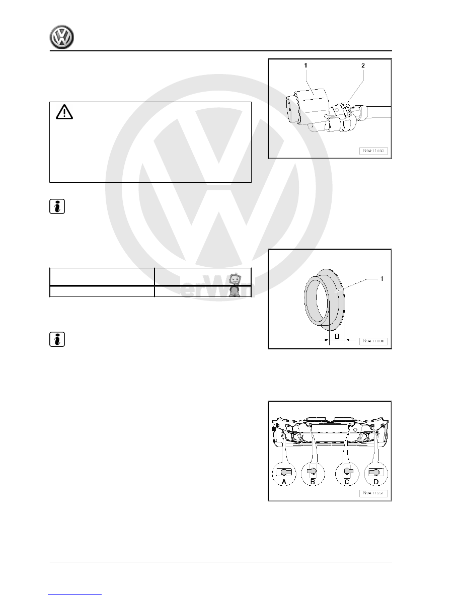
Assignment of parking aid sender on inside of rear bumper cover:
A - left outer
B - left centre
C - right centre
D - right outer

346


Note

When mounting the sender, make sure that the isolation ring

is correctly mounted on the sender head and does not ride or

roll up on insertion into the sender holder.

Both locking lugs of sender holder must audibly engage when

installing the sender.

– After installing the sender, check that the sender is correctly

seated in the bracket. Visible on the outer side of the bumper,

dimension -a- of the ring gap between the sender head and

bumper cover must be even all around.

14.11

Bonding sender holder in bumper cover

14.11.1 Bonding sender holder in bumper cover

The bonding process for the sender retainers in the front and rear

bumper covers is performed in the same manner. The bonding

area on the inside of the bumper cover is marked as a field around

the punched hole to assist in aligning the sender retainer during

the bonding process. Ensure that the material temperature of the

bumper cover and the sender holder lies between 15 ? and 25 ?.

14. Parking aid    

347


– Apply adhesion promoter „Scotchmount 4298“ evenly to

marked bonding area -1-

– Allow adhesion promoter to flash-off for approx. 5 minutes.
– Note correct position for bonding the sender holder.
Front bumper cover 

⇒ page 346

Rear bumper cover 

⇒ page 344

– Peel both protective foils off bonding surface of sender holder

-2- until a grey surface appears.

– Align sender retainer -2- in marked bonding area -1- so that a

uniform edge of approx. 3 mm is created.

Note

Ensure that the cut-out for the sender connector in the sender

holder is pointing in the correct direction as shown in the respec‐

tive allocation. The sender wiring is too short if the sender holder

is fitted incorrectly.

– Press sender holder -2- onto bumper cover for approx. 10

seconds using a high pressure.

Note

The pressure and the period are critical for the bonding proper‐

ties!

14.11.2 Bonding sender holder in radiator grille

Ensure when bonding the sender retainer in the radiator grille that

the sender retainer is aligned centrally in the punched hole in the

radiator grille as the sender holder does not have a shoulder. If

the sender holder is not aligned exactly centrally in the punched

hole in the radiator grille the isolation ring (black silicone ring) will

be under pressure from the sender ring, once installed. This may

adversely affect the function of the parking aid system. Ensure

the material temperature of the radiator grille and the sender

holder lies between 15 ? and 25 ?.

348


1 - Parking aid senders
2 - Decoupling ring
3 - Sender holder
4 - Bonding surface on inside of bumper
– Apply adhesion promoter „Scotchmount 4298“ evenly to bond‐

ing area around punched hole.

– Allow adhesion promoter to flash-off for approx. 5 minutes.
– Note correct position for bonding the sender holder.
Front bumper cover 

⇒ page 347

– Insert sender -1- into sender holder -3- until both locking de‐

vices audibly engage.

– Peel both protective foils off bonding surface of sender holder

-3- until a grey surface appears.

– Align sender head exactly centrally in punched hole in radiator

grille.

Note

If the sender head is not aligned exactly centrally in the punched

hole in the radiator grille, the isolation ring (black silicone ring) will

be under pressure from the sender ring, once installed, which may

adversely affect the function of the parking aid system.

– Firmly press sender holder onto radiator grille for approx. 10

seconds.

Note

The pressure and the period are critical for the bonding proper‐

ties!

14.12

Renewing parking aid senders

If a new parking aid sender is installed, the sender head must be

first painted in the colour of the bumper cover. The following pre‐

requisites must be adhered to when painting the senders to

ensure the function of the parking aid system is not adversely

affected.
Painting senders
– Remove isolation ring (black silicone ring) from new sender

head.

14. Parking aid    

349


Content   ..  843  844  845  846   ..