Volkswagen Golf Variant / Jetta. Manual - part 830


  Index      Volkswagen     Volkswagen Golf Variant (2007), Jetta (2005) - service repair manual


Search            


Content   ..  828  829  830  831   ..


Volkswagen Golf Variant / Jetta. Manual - part 830


Note

The headlight does not have to be removed to change the

bulb.

The following diagrams show renewal of the left side light bulb

-M1- in the left headlight.

Caution

♦ Switch off ignition and all electrical consumers.
♦ Remove the ignition key.

Removing
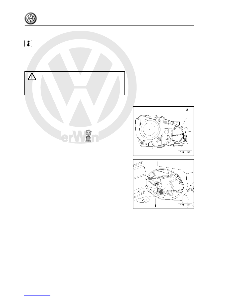
– Release cover cap -2- by turning it anti-clockwise and remove.

– Taking connected wiring lengths into consideration, pull bulb

holder -1- together with left side light bulb -M1- out of reflector.

286


Installing

Caution

♦ When installing cover cap, ensure that it seats properly.

The ingress of water will lead to permanent damage to the

headlight.

♦ Do not touch glass envelope when fitting bulb. Fingers

leave traces of grease on the glass envelope, which evap‐

orate when the bulb is switched on and cause the glass

envelope to cloud over.

Carry out installation in the reverse sequence, noting the follow‐

ing:
– Check headlight functions.

4.6

Headlight starter for gas discharge bulb

The left headlight starter for gas discharge bulb -J426- / right

headlight starter for gas discharge bulb -J427- is located on the

underside of the respective headlight housing.

4.6.1

Removing and installing headlight start‐

er for gas discharge bulb

Note

The following illustrations show removing or installation of right

headlight starter for gas discharge bulb -J427- for the right head‐

light. Left headlight starter for gas discharge bulb -J426- in left

headlight is removed and installed in same way.

Caution

♦ Switch off ignition and all electrical consumers.
♦ Remove the ignition key.

Removing
– Remove headlight 

⇒ page 280

 .

4. Headlights with gas discharge bulbs and cornering lights (from MY2010)    

287


When right headlight starter for gas discharge bulb -J427- is

pulled off from headlight housing, electrical connectors are simul‐

taneously disconnected.

– Pull right headlight starter for gas discharge bulb -J427- -1- at

right angles out of headlight housing.

Installing
Carry out installation in the reverse sequence, noting the follow‐

ing:

Caution

Ensure seal is seated correctly when installing right headlight

starter for gas discharge bulb -J427- . The ingress of water will

lead to permanent damage to the headlight.

– Tighten all threaded connections to specified torques

⇒ page 279

 .

– Check headlight functions.

4.7

Power output module for headlight

Power output module for left headlight -J667- / power output mod‐

ule for right headlight -J668- is located on the underside of the

respective headlight housing.

4.7.1

Removing and installing power output

module for headlight

Note

The following illustrations show removing or installation of the

power output module for headlight -J668- for the right headlight.

For the left headlight, removing or installation is carried out in the

same way.

Caution

♦ Switch off ignition and all electrical consumers.
♦ Remove the ignition key.

Removing
– Remove headlight 

⇒ page 280

 .

288


When right power output module for headlight -J668- is pulled off

from headlight housing, electrical connectors are simultaneously

disconnected.

– Pull right power output module for headlight -J668- -1- at right

angles out of headlight housing.

Installing
Carry out installation in the reverse sequence, noting the follow‐

ing:

Caution

When  installing  right  power  output  module  for  headlight  -

J668- , ensure that the seal is seated correctly. The ingress of

water will lead to permanent damage to the headlight.

– Tighten all threaded connections to specified torques

⇒ page 279

 .

Note

Control unit for headlight range control -J431- must be recoded if

a new power output module for right headlight -J668- is installed

⇒ page 291

 . Then subsequently perform the basic setting of

headlights ⇒ Maintenance ; Booklet  20.1 ; Descriptions of work .

– Check headlight functions.

4.7.2

Checking power output module for

headlight

Special tools and workshop equipment required
♦ Vehicle diagnosis, testing and information system -VAS

5051B-

The following procedure enables you to test the power output

module for left headlight -J667- / power output module for right

headlight -J668- .
Procedure
– Connect vehicle diagnosis, testing and information system -

VAS 5051B- .

4. Headlights with gas discharge bulbs and cornering lights (from MY2010)    

289


Content   ..  828  829  830  831   ..