Volkswagen Golf Variant / Jetta. Manual - part 555


  Index      Volkswagen     Volkswagen Golf Variant (2007), Jetta (2005) - service repair manual


Search            


Content   ..  553  554  555  556   ..


Volkswagen Golf Variant / Jetta. Manual - part 555


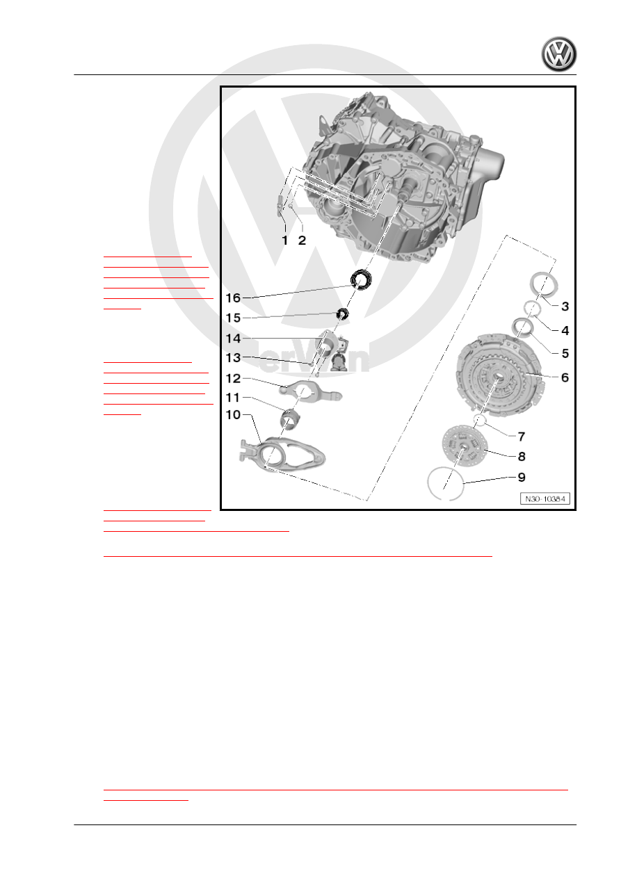
❑ For the large engaging

lever “K 1”

❑ Is not replaced

2 - Ball Stud

❑ For the small engaging

lever “K 2”

❑ Always replace when

replacing the dual clutch

3 - Shim “SK 1”

❑ Selecting thickness. Re‐

fer to

⇒ “2.3  K 1 and K 2

Clutch Engaging Bear‐

ing Position, Adjusting,

Transmission Produc‐

tion Date from 06/2011”,

page 45

 .

4 - Shim “SK 2”

❑ Selecting thickness. Re‐

fer to

⇒ “2.3  K 1 and K 2

Clutch Engaging Bear‐

ing Position, Adjusting,

Transmission Produc‐

tion Date from 06/2011”,

page 45

 .

5 - Small Engaging Bearing for

“K 2”

❑ Always replace when

replacing the dual clutch

6 - Dual Clutch

❑ Removing. Refer to

⇒ “2.2 Dual Clutch, Re‐

moving, Transmission

Production Date from 06/2011”, page 42

 .

❑ Installing. Refer to

⇒ “2.4 Dual Clutch, Installing, Transmission Production Date from 06/2011”, page 58

 .

7 - Circlip

❑ Always replace after removing

8 - Hub
9 - Circlip

❑ Always replace after removing

10 - Large Engaging Lever for “K 1”

❑ With engaging bearing
❑ Always replace when replacing the dual clutch

11 - Guide Sleeve Upper Section

❑ For the small engaging lever “K 2”
❑ Removed and installed together with the guide sleeve lower section

12 - Small Engaging Lever for “K 2”

❑ Is removed and installed together with the guide sleeve upper section and lower section
❑ Refer to

⇒ “2.3  K 1 and K 2 Clutch Engaging Bearing Position, Adjusting, Transmission Production Date from

06/2011”, page 45

2. Dual Clutch, Removing and Installing, from Transmission Production Date 06/2011    

41

❑ 8 Nm +90°
❑ Always replace after removing

14 - Guide Sleeve Lower Section

❑ For the small engaging lever “K 2”
❑ Removed and installed together with the guide sleeve upper section

15 - Seal

❑ For the inner input shaft
❑ Replacing. Refer to 

⇒ “3 Clutch-Side Seals, Removing and Installing”, page 63

 .

16 - Seal

❑ For the outer input shaft
❑ Replacing. Refer to 

⇒ “3 Clutch-Side Seals, Removing and Installing”, page 63

 .

2.2

Dual Clutch, Removing, Transmission

Production Date from 06/2011

Special tools and workshop equipment required
♦ T-Handle Hook - 3438-
♦ Engine Bung Set - VAS6122-
♦ Support Bridge - T10323-
♦ -T10356/5- from the Subframe Bushing Assembly Tool Kit -

T10356-

♦ Puller - Clutch - T10373-
♦ Clutch Press Piece - T10376-
Requirement
• The transmission is removed and mounted to the engine/

transmission holder. Refer to

⇒ “6 Transmission, Transporting and Securing To Assembly

Stand”, page 191

 .

• The DSG Transmission Mechatronic - J743- is installed in the

transmission.

– Remove both breather caps -arrows- and seal with clean oil-

tight plugs from the Engine Bung Set - VAS6122- for example.

Caution

The vent cap on the Mechatronic will be destroyed during re‐

moval and must be replaced.
Checking the hydraulic fluid level for the Mechatronic is not

possible. The Mechatronic vent must be sealed oil-tight before

performing any assembly work.
Fluid that has leaked out of the Mechatronic hydraulic area may

not be refilled or checked. Replace the Mechatronic if fluid is

leaking.

42

the clutch facing up.

Note

The clutch is removed upward. The Mechatronic stays on the

transmission.

– Remove the circlip on the hub -arrow-.

– Remove the hub using T-Handle Hook - 3438- and a screw‐

driver.

Note

The position of the “K 1” and “K 2” engaging bearings must be

adjusted later when clutch components are replaced. It is advis‐

able to determine dimension “B” for the measurements. Refer to

⇒ “2.3  K 1 and K 2 Clutch Engaging Bearing Position, Adjusting,

Transmission Production Date from 06/2011”, page 45

 .

– Remove the circlip -arrow- for the clutch

.

If It Is Not Possible to Remove the Locking Ring

Note

The clutch is »jamming« the circlip from underneath if the cir‐

clip cannot be removed.

If this is the case, press the clutch downward as described in

the following. The circlip will then be relieved. Never hit the

clutch or the shaft with a hammer.

Always replace the locking ring.

2. Dual Clutch, Removing and Installing, from Transmission Production Date 06/2011    

43

sion flange, as illustrated.

– If necessary, even out the gaps with Assembly Tool - 5 -

T10356A/5- for example.

– Tighten the bolts -A- hand-tight.

Note

Secure the bolts -A- with a nut, if needed.

Caution

Danger of damaging the clutch and other components.

• Push the clutch down gently without pressing.

– Turn the spindle against the Clutch Press Piece - T10376- to

lower it.

– Remove the locking ring -arrow- from the clutch.

WARNING

Do not re-use the locking ring.

Continuation for Removing the Locking Ring
– Insert the Puller - Clutch - T10373- into the clutch and remove

the clutch.

– Remove the clutch together with the Puller - Clutch - T10373- .

44


Content   ..  553  554  555  556   ..