Volkswagen Golf Variant / Jetta. Manual - part 529


  Index      Volkswagen     Volkswagen Golf Variant (2007), Jetta (2005) - service repair manual


Search            


Content   ..  527  528  529  530   ..


Volkswagen Golf Variant / Jetta. Manual - part 529


⇒ “1.10 Selector Mechanism, Adjusting”, page 76

 .

9 - Hex Nut

❑ 23 Nm
❑ Self-locking
❑ Replace after removing

10 - Lock Washer

❑ Replace after removing
❑ Not needed for the plastic relay lever

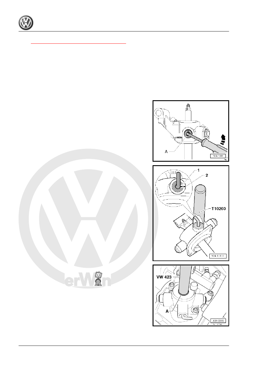
Removing the locking elbow -A- from the shift cover
– Remove the outer part of the locking elbow.
– Pry out the locking elbow with a screwdriver.

Drive the locking elbow in the shift cover.
Installation position:
Marking-1- faces toward marking -2- on selector cover.

Insert sealing ring -A- as far as stop

132

Shift Forks, Disassembling and As‐

sembling

Special tools and workshop equipment required
♦ Press Plate - VW402-
♦ Subframe Support Tool - Press Piece - 3290/1-
♦ Press Piece - Multiple Use - VW431-
♦ Subframe Bushing Tool Kit - 3301-
♦ Press Piece - Multiple Use Spacer Sleeve - VW472/2-
♦ Valve Guide/Clutch Release Push Rod Seal Drift - 10-206-
♦ Assembly Mandrel for Gear Selector Rod - 10-508-
♦ Pry Lever - 80-200-
♦ Spring Strut Compressor - 2070-

Note

The shift fork group (-item 1- 

⇒ Item 1 (page 134)

 ) does not need to be disassembled to remove and install

shift segments, lock washers and angular contact ball bearings.

9. Shift Forks, Disassembling and Assembling    

133

shift Rails
2 - 3rd/4th Gear Shift Segment

❑ Identification. Refer to

⇒ Fig. ““Identification of

selector segments and

5th gear shift fork with

selector segments”“ ,

page 135

 .

❑ Selector segment must

still rotate easily after

assembly

3 - Angular Contact Ball Bear‐

ing

❑ Quantity: 4
❑ Removing. Refer to

⇒ Fig. ““Removing the

Angular Contact Ball

Bearing”“ , page 136

 .

❑ Installing the bearing in‐

ner race into the outer

race. Refer to

⇒ Fig. ““Installing the an‐

gular contact ball bear‐

ing inner race -A- into

the outer race”“ ,

page 136

❑ Installing. Refer to

⇒ Fig. ““Installing the an‐

gular contact ball bear‐

ing into the shift fork”“ ,

page 136

 .

4 - Lock Washer

❑ Replace after removing
❑ Removing. Refer to

⇒ Fig. ““Removing the

lock washer”“ , page 135

 .

❑ Installing. Refer to 

⇒ Fig. ““Installing the lock washer”“ , page 135

 .

5 - 1st/2nd Gear Shift Segment

❑ Identification. Refer to

⇒ Fig. ““Identification of selector segments and 5th gear shift fork with selector segments”“ , page 135

 .

❑ The shift segment must still rotate easily after the lock washer is installed.
❑ Shift fork with selector segment

6 - 5th Gear Shift Fork with Selector Segments

❑ Selector segments are connected to shift fork and cannot be separated.
❑ Identification. Refer to

⇒ Fig. ““Identification of selector segments and 5th gear shift fork with selector segments”“ , page 135

 .

7 - Mounting Pin

❑ for 5th gear shift fork

134

lector segments
Dimension -a-
1 - 1st/2nd Gear Shift Segments = 10.2 mm
2 - 3rd/4th Gear Shift Segment = 78.6 mm
3 - 5th Gear Shift Fork with Shift Segments = 79.5 mm

1st/2nd gear shift fork with shift segments
Dimension -a- = 75 mm

Removing the lock washer
– Secure shift fork in vise with protective jaws -B-.
– Pry off the lock washer -A- in the direction of the -arrow-.

Installing the lock washer
– Press the lock washer in the groove in the shift segment using

a socket wrench

Note

The shift segment must still rotate easily after the lock washer is

installed.

A - 10 mm socket wrench
B - Protective Jaws

9. Shift Forks, Disassembling and Assembling    

135


Content   ..  527  528  529  530   ..