Volkswagen Golf Variant / Jetta. Manual - part 525


  Index      Volkswagen     Volkswagen Golf Variant (2007), Jetta (2005) - service repair manual


Search            


Content   ..  523  524  525  526   ..


Volkswagen Golf Variant / Jetta. Manual - part 525


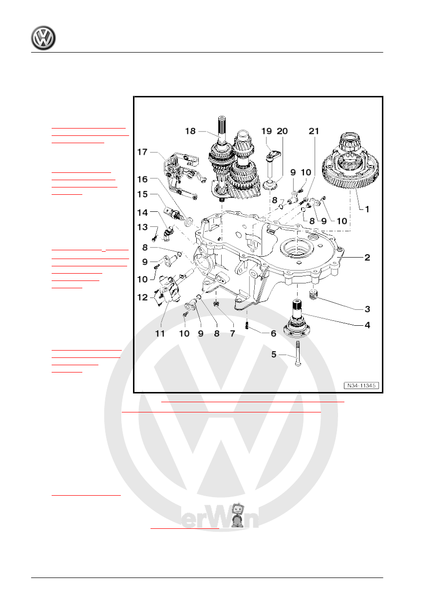
Overview - Input Shaft, Output Shaft, Differential Selector Mechanism and

Shift Rods, Removing and Installing

1 - Differential

❑ Disassembling and as‐

sembling. Refer to

⇒ “2.1 Differential, Dis‐

assembling and Assem‐

bling”, page 173

 .

2 - Transmission Housing

❑ Servicing. Refer to

⇒ “7 Transmission

Housing and Clutch

Housing, Servicing”,

page 127

 .

❑ Shim S1 for the differen‐

tial outer race/tapered

roller bearing if deleted

from transmission date

of manufacture

04/12/2006. Refer to

⇒ Fig. ““Shim S1 for the

outer race/tapered roller

bearing is deleted as of

production date

04/12/2006.”“ ,

page 179

❑ Outer race/tapered roll‐

er bearing seat adapted

in transmission housing

3 - Oil Drain Plug

❑ Tightening specifica‐

tion. Refer to

⇒ Fig. ““Different Ver‐

sions of Fluid Fill and

Drain Plugs”“ ,

page 111

4 - Flange Shaft with Pressure

Spring

❑ Removing and installing. Refer to 

⇒ “6.6 Disassembly and Assembly Sequence”, page 117

 .

❑ Assembling. Refer to 

⇒ “2.1 Differential, Disassembling and Assembling”, page 173

 .

5 - Bolt

❑ 25 Nm

6 - Bolt

❑ 5 Nm and 90° additional turn
❑ Self-locking
❑ Replace after removing
❑ for securing bearing mount with grooved ball bearing for input and output shaft -item 18-

⇒ Item 18 (page 117)

7 - Hex Collar Bolt

❑ 23 Nm
❑ For shift mechanism -item 17- 

⇒ Item 17 (page 117)

❑ Self-locking
❑ Replace after removing

116

❑ Replace after removing

9 - Pivot Pin
10 - Bolt

❑ 5 Nm and 90° additional turn
❑ Replace after removing

11 - Gearshift Shaft with Gearshift Cover

❑ (Shift unit)
❑ Servicing. Refer to 

⇒ “8 Shift Unit, Servicing”, page 131

 .

12 - Bolt

❑ 5 Nm and 90° additional turn
❑ Replace after removing

13 - Bolt

❑ 6 Nm

14 - Transmission Neutral Position Sensor - G701-

❑ For vehicles with the Start/Stop System

15 - Back-Up Lamp Switch - F4-

❑ 20 Nm
❑ Short after series introduction of transmission with permanent seal

16 - Seal

❑ If present, replace after removing
❑ Not installed on all transmissions

17 - Selector Mechanism

❑ (Shift forks)
❑ Servicing. Refer to 

⇒ “9 Shift Forks, Disassembling and Assembling”, page 133

 .

18 - Input Shaft with Output Shaft and Bearing Mount/Grooved Ball Bearing

❑ If bearing mount is removed from transmission housing, it must always be replaced
❑ Bearing Mount, Removing and Installing. Refer to -item 8- 

⇒ Item 8 (page 150)

❑ Input Shaft, Disassembling and assembling. Refer to

⇒ “1.1 Input Shaft, Disassembling and Assembling”, page 149

❑ Output Shaft, Disassembling and assembling. Refer to

⇒ “2.1 Output Shaft, Disassembling and Assembling”, page 158

19 - Reverse Gear Axle
20 - Reverse Drive Gear
21 - Bolt

❑ 25 Nm and 45° additional turn
❑ Replace after removing
❑ For securing reverse gear axle

6.6

Disassembly and Assembly Sequence

⇒ “6.6.1 Transmission, Disassembling”, page 117
⇒ “6.6.2 Transmission, Assembling”, page 121

6.6.1

Transmission, Disassembling

Special tools and workshop equipment required
♦ Holding Fixture - VW313-

6. Transmission, Disassembling and Assembling    

117

⇒ page 118

 )

or

♦ Gearbox Support - 3221A-
♦ Guide Pin - T10079-
♦ Not needed: Press Piece - 31.5mm - VW418A-
♦ Press Piece - Rod - VW407-
♦ Bearing Installer - Wheel Bearing/Ball Bearing - 3074-
♦ Press Piece - T10080-
♦ Press Piece - Block - T10083-
♦ Press Piece - Block - Washer - T10083/1-
♦ Shop Crane - Drip Tray , for example -VAS6208-
♦ Press Piece - T10085-
Removing transmission housing cover, clutch housing, selector

shaft with selector cover, input shaft, output shaft, differential and

selector mechanism.
– Check the Gearbox Support - 3221A- and if necessary modify.
– If necessary drill a 11.0 mm diameter hole -arrow-.
– The label the Gearbox Support - 3221- as -3221A- .

– Secure the transmission on the Gearbox Support - 3221A-

-arrows-.

– Place the Shop Crane - Drip Tray , for example -VAS6208-

underneath.

– Drain the transmission fluid.

118

and guide sleeve -arrows-.

– Remove the right flange shaft securing bolt -B-.
– Install 2 bolts into the flange and counterhold the flange shaft

with a pry bar.

– Remove the flange shaft with spring, thrust washer and ta‐

pered ring.

– Remove the transmission housing cover -arrow-.

– Remove the mounting pin -1- for the 5th gear shift fork -2- and

remove the shift fork.

– Remove the 5th gear synchronizer hub locking ring -3-.
– Remove the locking ring -4- from the 5th gear wheel.
– Remove the 5th gear synchronizer hub and drive gear.

6. Transmission, Disassembling and Assembling    

119


Content   ..  523  524  525  526   ..