Volkswagen Golf Variant / Jetta. Manual - part 385


  Index      Volkswagen     Volkswagen Golf Variant (2007), Jetta (2005) - service repair manual


Search            


Content   ..  383  384  385  386   ..


Volkswagen Golf Variant / Jetta. Manual - part 385


oil supply line.

– Remove the camshaft toothed belt sprocket and remove the

camshaft hub using the Puller - Camshaft Sprocket - T10052- .

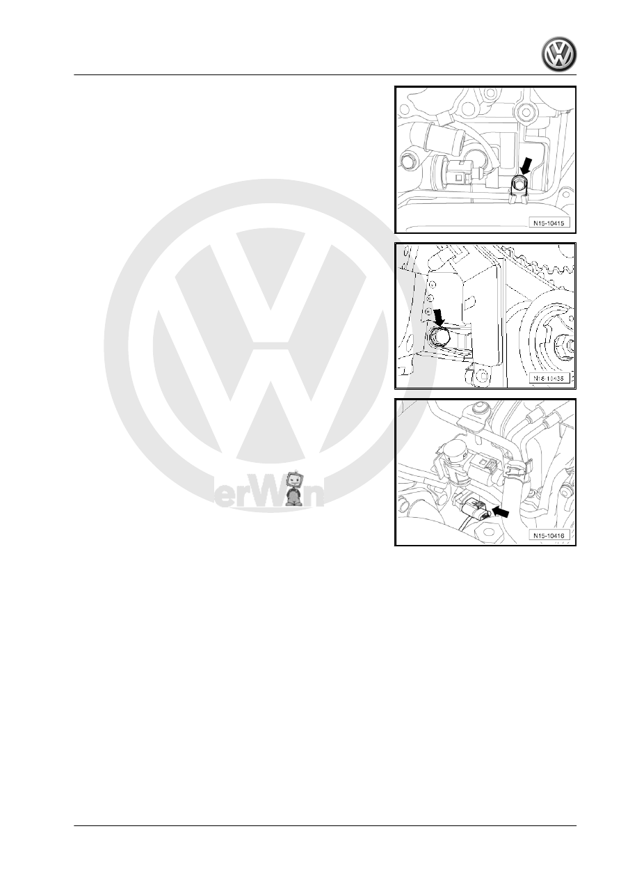
– Remove the bolt -arrow- on the toothed belt guard.
– Remove the nut on the toothed belt tensioning roller.

– Disconnect the connector for the Camshaft Position Sensor -

G40- -arrow-.

1. Cylinder Head    

123

Note

A second technician is needed to remove the cylinder head.

The toothed belt tensioning roller is pulled off the stud bolt

when prying the cylinder head out.

The turbocharger oil return line is pulled out of the support

when lifting the cylinder head out.

– Lift the cylinder head first on the transmission side and guide

it out of the toothed belt guard. Be careful not to let the toothed

belt tensioning roller fall.

– Lay the cylinder head down so that the oil return line is not

bent. Place a wooden block under the exhaust manifold if nec‐

essary.

Installing

Caution

There is a risk of damaging sealing surfaces:

♦ Carefully remove the sealant residue from the cylinder

head and cylinder block.

♦ Make sure that no long grooves or scratches result.

Risk of damaging the cylinder block:

♦ There must be no oil or coolant in the blind holes for the

cylinder head bolts in the cylinder block.

Risk of the cylinder head gasket leaking:

♦ Carefully remove all lapping and sanding residue.
♦ Only unpack the new cylinder head gasket immediately

before installing.

♦ To prevent the cylinder head gasket silicone layer and re‐

cessed area from being damaged, always handle the seal

extremely carefully.

Risk of damaging open valves:

♦ If a replacement cylinder head is installed, only remove

the accompanying plastic base immediately before instal‐

ling to protect the open valves.

Risk of damaging valves and piston heads after working on the

valvetrain:

♦ To ensure valves do not strike pistons when starting, care‐

fully rotate engine at least two full revolutions.

♦ Before installing, check if the oil return pipe decoupling

element is bent or stretched. If this is the case, there could

be micro tears which could result in leaks. If necessary,

replace the oil return pipe before installing the cylinder

head.

124

Always replace cylinder head bolts.

Carefully remove residual sealant from cylinder head and cyl‐

inder block. Make sure that no long grooves or scratches

result. When using sand paper, grit must not be below 100.

Thoroughly remove all sanding and lapping residue.

Only unpack the new cylinder head gasket immediately before

installing.

Handle the seal carefully. Damages to the silicone layer and

in areas of recesses may result in leaks.

– Before mounting the cylinder head, remove the Crankshaft

Stop - T10050- and rotate the crankshaft back opposite the

direction of engine rotation until all of the pistons are nearly

even under TDC.

– Place the cylinder head gasket with the identification upward.

– To center, slide the Guide Tool - Cylinder Head - 3070- into

the outer holes on the intake side.

Note

The tensioning roller must be placed on the stud bolt when mount‐

ing the cylinder head.

– Install the cylinder head, insert the eight cylinder head bolts

and tighten them by hand.

– Remove the guide pins using the guide pin handle from Guide

Tool - Cylinder Head 3070, and then insert the cylinder head

bolts.

– Tighten the cylinder head in the tightening sequence, in four

stages as follows:

1 - Tighten using Torque Wrench:
Step I = 30 Nm
Step II = 50 Nm
2 - Tighten further using a solid wrench:
Step III = 

1

/4 (90 °) turn

Step IV = 

1

/4 (90 °) turn

– Secure the rear toothed belt guard on the cylinder head.
– Install the hub and the camshaft sprocket.
– Use the Diesel Injection Pump Locking Pin - 3359- to secure

the camshaft and the high pressure pump.

1. Cylinder Head    

125

and secure the crankshaft with the Crankshaft Stop - T10050- .

– Install the toothed belt. Refer to 

⇒ , page 98

 .

Further installation is the reverse order of removal. Note the fol‐

lowing:
– Install the cylinder head cover. Refer to

⇒ “1.5 Cylinder Head Cover, Removing and Installing”,

page 90

 .

– Install the ribbed belt. Refer to

⇒ “1.4 Ribbed Belt, Removing and Installing”, page 47

 .

– Fill the coolant. Refer to

⇒ “1.9 Coolant, Draining and Filling”, page 209

 .

– Perform a road test and check the DTC memory.

1.8

Vacuum Pump, Removing and Installing

Note

When replacing the cylinder head or cylinder head gasket, all

of the coolant must be replaced.

Cylinder heads with cracks between the valve seats can con‐

tinue to be used without reducing service life, as long as the

tears have a width of maximum 0.5 mm.

After working on the valvetrain and engine, carefully rotate by

hand at least two full turns to be sure that valves do not strike

pistons when starting.

Always replace the self-locking nuts, seals, gaskets and

clamps.

Special tools and workshop equipment required
♦ Torque Wrench 1331 5-50Nm - VAG1331-

DANGER!

Do not disassemble the vacuum pump under any circumstan‐

ces because it can cause the vacuum component to malfunc‐

tion. The result would be brake booster failure.

Removing:
– Remove the engine cover. Refer to

⇒ “1.4 Engine Cover, Removing and Installing”, page 90

 .

– Remove the air filter housing. Refer to

⇒ “3.14 Overview - Air Filter”, page 335

 .

126


Content   ..  383  384  385  386   ..