Volkswagen Golf Variant / Jetta. Manual - part 333


  Index      Volkswagen     Volkswagen Golf Variant (2007), Jetta (2005) - service repair manual


Search            


Content   ..  331  332  333  334   ..


Volkswagen Golf Variant / Jetta. Manual - part 333


out of the center tunnel. Make sure the cord is pulled through

far enough so that it can reached from inside the engine com‐

partment.

– Remove the selector lever cable cord.

Note

The selector mechanism is available only together with the se‐

lector housing and selector lever cable. Refer to the Parts Cata‐

log.

Installing
Install in reverse order of removal. Note the following:
A second technician is needed for threading the selector lever

cable from the passenger compartment into the engine compart‐

ment.

Note

Do not bend or kink the selector lever cable.

Do not lubricate the selector lever cable.

Tightening specifications. Refer to

⇒ “5.3 Overview - Selector Mechanism, Vehicles from

03/2009”, page 72

 .

– Secure the cord that was involved when removing the selector

mechanism from the engine compartment on the end of the

selector lever cable.

– Guide the selector mechanism and selector lever cable

through the opening in the center tunnel.

– From the engine compartment, have the second technician

pull the cord with the selector lever cable through the tunnel

until it is possible to attach the selector lever cable to the cable

bracket.

– Remove the selector lever cable cord.

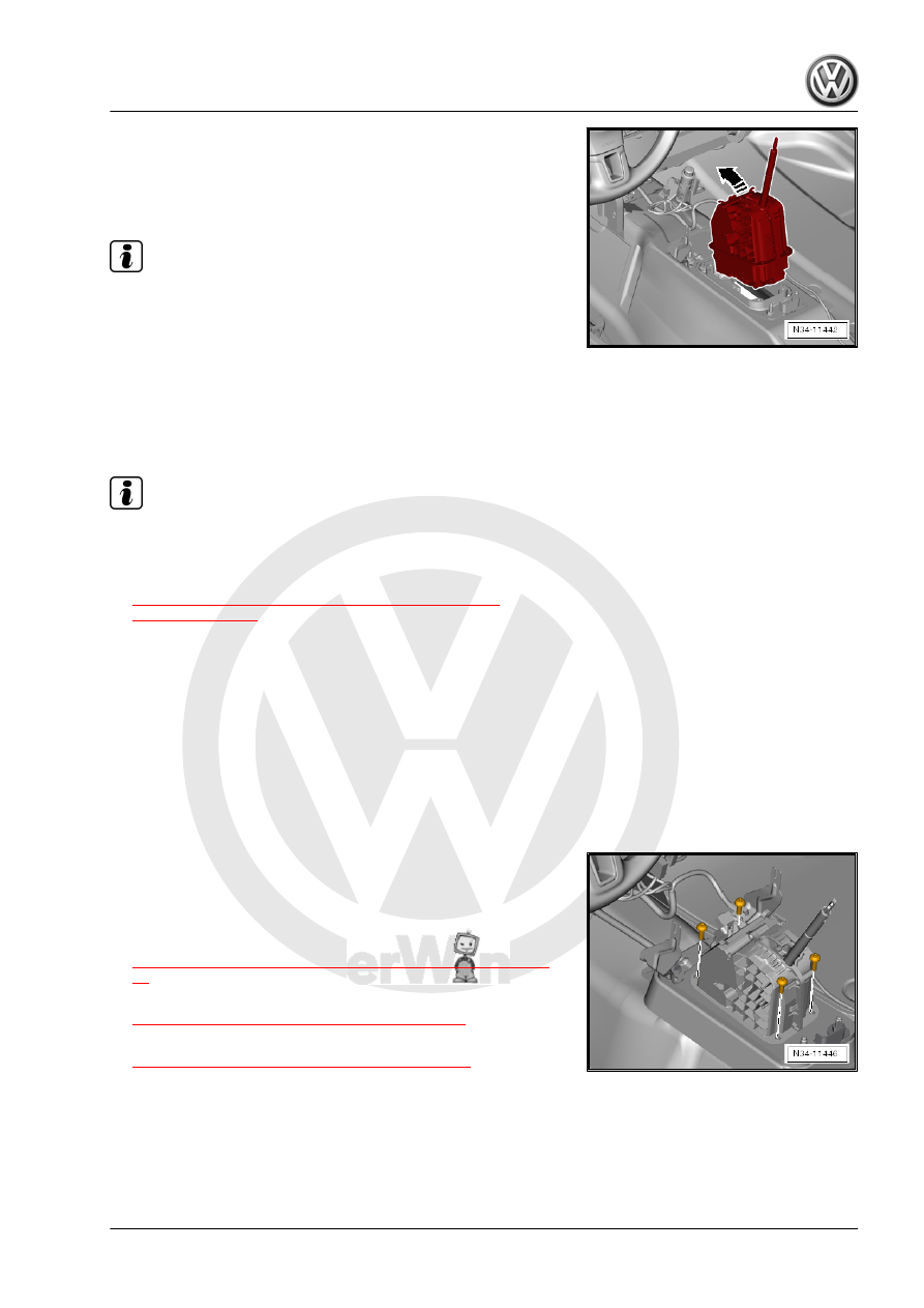
– Attach the selector mechanism to the selector housing with

four bolts.

68 ; Center Console .

– Install the selector lever handle. Refer to

⇒ “5.8 Selector Lever Handle, Removing and Installing”, page

82

 .

– Adjust the selector lever cable. Refer to

⇒ “5.6 Selector Lever Cable, Adjusting”, page 80

 .

– Check the selector mechanism. Refer to

⇒ “5.10 Selector Mechanism, Checking”, page 86

 .

Housing, Removing and Installing .

System; Air Filter Housing, Removing and Installing .

5. Selector Mechanism    

79

Selector Lever Cable, Checking

Brief Description
The selector lever cable must be removed from the transmission

in order to check it for ease of movement. Do not let the removed

end touch anything.
Then the selector lever is moved and the selector lever cable in‐

stalled again on the transmission.
After that, the selector lever cable must be adjusted. Refer to

⇒ “5.6 Selector Lever Cable, Adjusting”, page 80

 .

Do not lubricate the selector lever cable connections.
Checking
– Move the selector lever into »P«.
– Remove the selector lever cable from the lever on the trans‐

mission.

– Move the selector lever from »P« to »S« and back to »P« sev‐

eral times.

• The selector lever must have ease of movement.
– Install the selector lever cable with new lock washers and the

»loosened« adjustment screw.

– Adjust the selector lever cable. Refer to

⇒ “5.6 Selector Lever Cable, Adjusting”, page 80

 .

5.6

Selector Lever Cable, Adjusting

Special tools and workshop equipment required
♦ Torque Wrench 1331 5-50Nm - VAG1331-
Selector Lever Cable Must Always Be Adjusted If:
♦ The selector lever cable was removed from the transmission.
♦ The engine and/or transmission were removed and installed.
♦ Sections of the subframe mount were removed and installed.
♦ The selector lever cable itself or the selector mechanism was

removed and installed.

♦ The engine/transmission position was changed, for example,

were installed without tension.

Adjusting
– Move the selector lever into “P”.

80

rear«.
– Pull the lever forward.

– Push the lever »to the rear« -arrow-.
“P” is in the Second Detent.

Note

Raise the vehicle to make sure the transmission is in “P” (park‐

ing lock is engaged). The front wheels must not turn together

in any direction.

The transmission is also in “P” if the vehicle does not move

with wheels spinning freely.

– Install the selector lever cable with the loosened adjusting

screw -arrow- and the new lock washer -A and B-.

– Tap the handle on the selector lever back and forth gently but

do not move it out of “P” under any circumstances.

This places the selector lever cable core in its optimal position.
– Tighten the adjusting bolt -arrow- to 13 Nm.
This ends the adjustment.

5. Selector Mechanism    

81

Selector Lever, Emergency Release

Do Not Remove the Handle
– Unclip the shift cover and hold it to the side.
– Press the brake or set the parking brake.
Vehicles through 02/2009
– Press on the yellow plastic piece from the right to the left in

direction of -arrow-.

– Or press it onto the solenoid pins.

Vehicles from 03/2009
– Push onto the yellow plastic part -arrow-.

5.8

Selector Lever Handle, Removing and

Installing

Brief Description
There are different handles depending on the model.
The handle is removed together with the shift cover.
Removing
– Move the selector lever into “D” position.

82


Content   ..  331  332  333  334   ..