Volkswagen Golf Variant / Jetta. Manual - part 314


  Index      Volkswagen     Volkswagen Golf Variant (2007), Jetta (2005) - service repair manual


Search            


Content   ..  312  313  314  315   ..


Volkswagen Golf Variant / Jetta. Manual - part 314


O-Rings, Gaskets and Seals

♦ Replace the O-rings, seals and gaskets.
♦ Flange shaft and selector shaft seals are illustrated as shaft

seals.

♦ After removing the gaskets and seals, check the contact sur‐

faces on the housing or shaft for burrs resulting from removal

or damage.

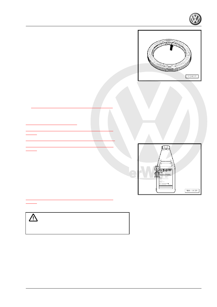
♦ Before installing the seals, lightly oil the outer circumference

and fill the space between the sealing lips -arrow- halfway with

Grease - G 052 128 A1- .

♦ Only use DSG® transmission fluid. Other lubricants cause

malfunctions.

♦ The open side of the gaskets point toward the fluid to be sealed

in.

♦ After installing, check transmission fluid level and fill. Refer to

⇒ “9.2 Fluid Level, Checking and Filling”, page 133

 .

1.5

DSG® Transmission Fluid

⇒ “1.5.1 Fluid Function”, page 3
⇒ “1.5.2 Transmission Fluid Filter, When To Change ”,

page 4
⇒ “1.5.3 Fluid and Fluid Level Troubleshooting”, page 4
⇒ “1.5.4 Transmission Fluid Drain and Check Plug A ”,

page 4

Shake the bottles before opening.
Fluid is available as an original part. Original part number. Refer

to the Parts Catalog.
The Quality of Transmission Fluid Is Crucial to Transmission

Function.
Do not mix additives into the transmission fluid. Do not fill with a

different transmission fluid.
Determine the correct fluid and other important information. Refer

to

⇒ “1.5.2 Transmission Fluid Filter, When To Change ”,

page 4

 .

The drained transmission fluid must not be used again.

Caution

Be very careful when handling transmission fluid. Dispose of

drained transmission fluid correctly.

1.5.1

Fluid Function

The fluid does not just »lubricate« the transmission.
Imagine: the filter also transports the finest differential abrasive

parts in both filters. The fluid makes sure the lubricating film does

not wear off the differential tooth flanks. At the same time, it acts

as a switch valve pressure medium to enable it to perform its

functions.
It also seals the selector lever and helps the synchronizer rings

when shifting gears. The fluid conserves and transports warmth

1. General Repair Information    

3

DSG® transmission fluid fulfills many requirements.
To maintain this degree of performance, the filter on the trans‐

mission should be replaced during the oil maintenance service.

1.5.2

Transmission Fluid Filter, »When To

Change«

The transmission fluid filter does not need to be changed in every

case.
Do Not Replace the Filter If
♦ The transmission fluid cooler or its O-rings were replaced and

no coolant has entered the transmission fluid.

♦ The selector shaft seal was replaced.
♦ The flange or stub shaft seal was replaced.
♦ Leaking Mechatronic covers, multi-plate clutch or oil pump

were replaced.

♦ The Transmission Input Speed Sensor - G182- with Clutch Oil

Temperature Sensor - G509- was replaced.

The Filter Must Be Replaced If
♦ The 60,000 km maintenance interval was reached.
♦ Coolant has entered the transmission fluid.
♦ Metal shavings were found in the transmission fluid.
♦ The clutch is burned or has a mechanical fault.

1.5.3

Fluid and Fluid Level Troubleshooting

Fluid and Fluid Level Troubleshooting
For more information regarding the fluid. Refer to

⇒ “1.5.1 Fluid Function”, page 3

 . But the fluid cannot disappear

»without a trace«.
Fluid can only be missing if it has leaked from the transmission.
Transmission Lubricated
– Determine where the fluid has leaked out of the transmission.

Repair this leak first. Fill with new transmission fluid and make

sure the level is »correct«. Refer to

⇒ “9 Transmission Fluid and Transmission Fluid Filter”,

page 132

 .

Filling the fluid »just in case« does not correct a malfunction. It

does not help to find the malfunction and it gives a false sense of

security.

1.5.4

Transmission Fluid Drain and Check

Plug -A-

Through transmission production date “09/20/2004”, transmis‐

sions were installed with two plugs.
Then the second plug was discontinued so that draining oil and

adjusting the oil level can both be done using the plug -A-.
A plastic overflow tube is located behind this plug (with 8 mm hex

socket head, tightening specification: 3 Nm). Its length deter‐

mines the fluid level in the transmission.

4

Bolts and Nuts

♦ Loosen or tighten bolts and nuts on covers or housing diago‐

nally.

♦ The tightening specifications given apply to unoiled bolts and

nuts.

♦ Use a wire brush to clean the threads of the bolts that were

installed with locking fluid. Install the bolts with Locking Fluid

- AMV 185 101 A1- .

♦ Clean all threaded holes containing self-locking bolts, with a

thread tap to remove any locking fluid residue. Otherwise the

bolts could shear the next time they are removed.

♦ Always replace self-locking bolts and nuts.

1.7

Electrical Components

Almost everyone has been shocked at one time or another when

coming into contact with a metal object. The reason for this is the

build-up of static electricity in the human body. This charge can

damage the electrical components in the transmission and the

selector mechanism when touching them.
– Touch a grounded object, such as, a water pipe or a vehicle

hoist, before working on electrical components. Do not touch

the connector terminals directly.

1. General Repair Information    

5

Troubleshooting

⇒ “2.1 Troubleshooting, General Information”, page 6
⇒ “2.2 Transmission Control Module Malfunction Behavior Infor‐

mation”, page 6
⇒ “2.3 Fault Finding, Special Information”, page 7

2.1

Troubleshooting, General Information

Before beginning any repair work, the cause of damage should

be determined using “Guided Fault Finding”.
Perform 

Guided Fault Finding

 using the Vehicle Diagnostic

Tester .

2.2

Transmission “Control Module Malfunc‐

tion Behavior” Information

The control module operates with highly developed software. This

software has the ability to execute electrical functions, monitor

and control within milliseconds. Everything modern transmission

electronics »have to offer« »is contained« in this control module.

This should also be kept in mind during troubleshooting.
However, no electronics can do what they were not designed to

do. Likewise, it is not possible to detect electronically where the

transmission housing is leaking and oil is escaping, for example.

However, it is possible to detect the effects of »low oil«. A failure

in “gear monitoring” would be recognized causing the control

module to respond that both clutches are open (no traction).
This should be known during troubleshooting and also when

working with the Volkswagen tester. It is possible that the cause

for the malfunction might not be found during 

Guided Fault

Finding

.

In addition to the highly developed software, much has been done

to protect the transmission should there be a malfunction (safety

features). And so, when necessary, malfunctions are saved and

a replacement program is started.
Control Module Behavior During A Malfunction
If a component in the transmission malfunctions, the control mod‐

ule reacts with a replacement function. In order to protect the

transmission, there are four different kinds of malfunctions:
1 - The malfunction is so minor that it is possible to continue

driving with a replacement program while maintaining driv‐

ing safety. The driver is not notified of this via the Selector

Lever Transmission Range Display - Y5- . The display

shows the selector lever position normally. If changes in

driving behavior can even be detected.

2 - The individual lever positions blink in the Selector Lever

Transmission Range Display - Y5- . This signals to the driver

that the gear selection is currently not possible. Example:

Driving in reverse, lever in “R” and vehicle drives backwards.

If “D” is engaged in this situation, the letter “D” blinks in the

Selector Lever Transmission Range Display - Y5- . In this

case, the control module prevents 1st gear from being en‐

gaged to avoid damaging the transmission. The gear is only

engaged when the vehicle is stopped. If testing this, do so

carefully!

3 - The Selector Lever Transmission Range Display - Y5- is

completely lit up and blinking. The selector lever position is

indicated/highlighted. Example: the transmission fluid tem‐

perature is too high. Reasons could include: towing a trailer

6


Content   ..  312  313  314  315   ..