Volkswagen Golf Variant / Jetta. Manual - part 264


  Index      Volkswagen     Volkswagen Golf Variant (2007), Jetta (2005) - service repair manual


Search            


Content   ..  262  263  264  265   ..


Volkswagen Golf Variant / Jetta. Manual - part 264


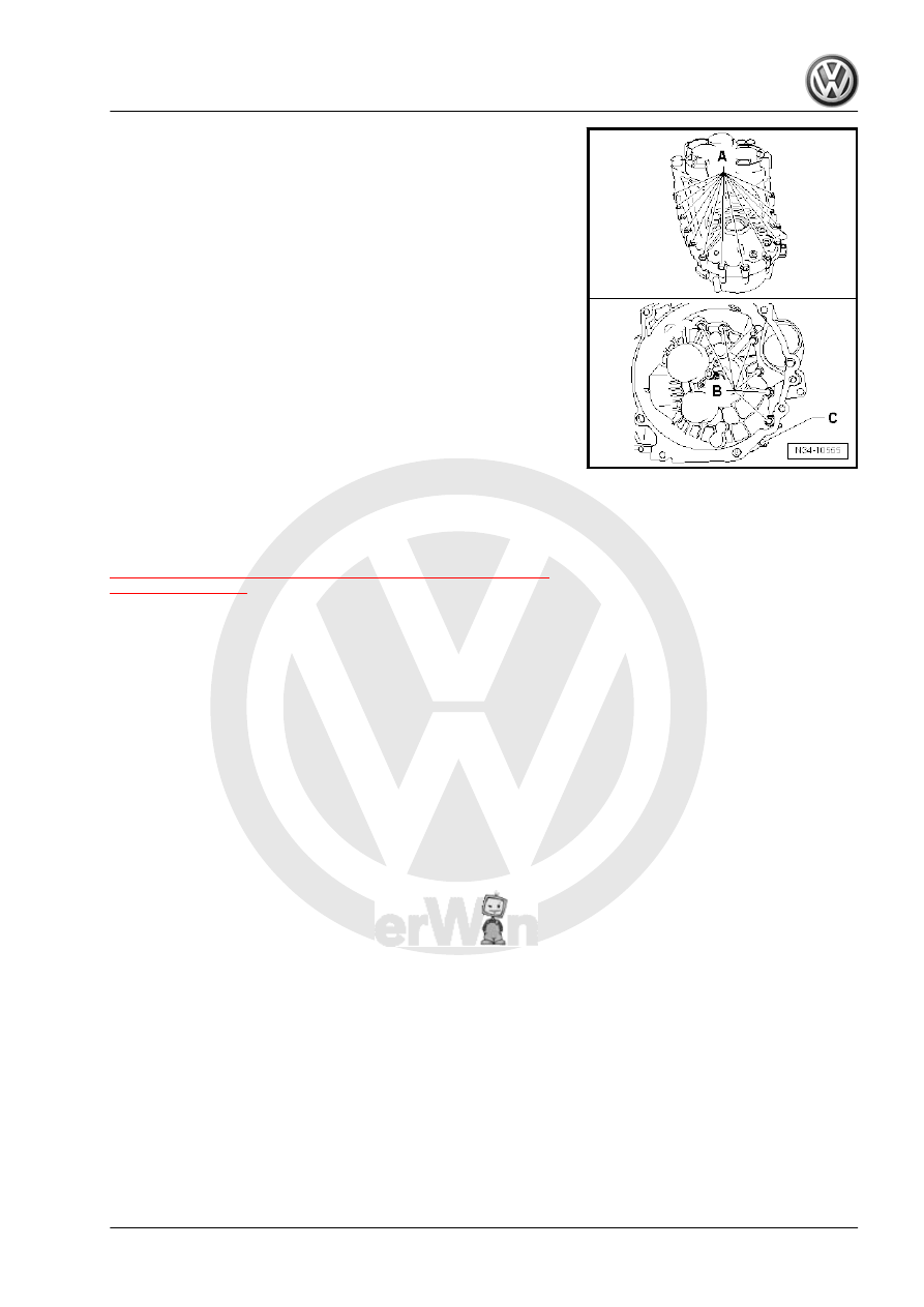
Attention to the Allocation
A - Bolt with permanent washer
B - Bolt without washer
C - Bolt with permanent washer

11.6

Overview - Input Shaft, Output Shafts,

Differentials and Shift Rods, Removing

and Installing, for FWD Vehicles

⇒ “11.6.1 Shafts and Gearshift Rods in Transmission Installation

Location”, page 233

11. Transmission, Disassembling and Assembling    

231

Shaft

❑ Disassembling and as‐

sembling. Refer to

⇒ “2.2 Output Shaft, 1st

to 4th Gears, Disassem‐

bling and Assembling”,

page 321

 .

❑ Installation position. Re‐

fer to

⇒ “11.6.1 Shafts and

Gearshift Rods in

Transmission Installa‐

tion Location”,

page 233

 .

2 - Gearshift Rod with 1st Gear

and 2nd Gear Shift Fork

❑ Installation position. Re‐

fer to

⇒ “11.6.1 Shafts and

Gearshift Rods in

Transmission Installa‐

tion Location”,

page 233

 .

3 - Gearshift Rod with 3rd Gear

and 4th Gear Shift Fork

❑ Installation position. Re‐

fer to

⇒ “11.6.1 Shafts and

Gearshift Rods in

Transmission Installa‐

tion Location”,

page 233

 .

4 - 5th, 6th and Reverse Gear

Output Shaft

❑ Disassembling and as‐

sembling. Refer to

⇒ “3 5th, 6th and Reverse Gear Output Shaft”, page 344

 .

❑ Installation position. Refer to

⇒ “11.6.1 Shafts and Gearshift Rods in Transmission Installation Location”, page 233

 .

5 - Gearshift Rod with 5th Gear and 6th Gear Shift Fork

❑ Installation position. Refer to

⇒ “11.6.1 Shafts and Gearshift Rods in Transmission Installation Location”, page 233

 .

6 - Reverse Gear Shift Fork

❑ Installation position. Refer to

⇒ “11.6.1 Shafts and Gearshift Rods in Transmission Installation Location”, page 233

 .

❑ Difference. Refer to 

⇒ Fig. ““Reverse Gear Shift Fork Differentiation”“ , page 278

❑ Servicing. Refer to 

⇒ “15 Shift Forks, Servicing”, page 277

 .

7 - Input Shaft

❑ Disassembling and assembling. Refer to 

⇒ “1.1 Overview - Input Shaft”, page 310

 .

❑ Replace grooved ball bearing on driveshaft after removing -item 6- 

⇒ Item 6 (page 311)

 .

8 - Reverse Shaft

❑ With a thrust washer

9 - Thrust Washer
10 - Bleeder

❑ Connect with clutch slave cylinder -item 14- 

⇒ Item 14 (page 233)

232

❑ Servicing. Refer to 

⇒ “13 Clutch Housing, Servicing”, page 269

 .

12 - Input Shaft Seal

❑ Replacing. Refer to 

⇒ “2.4 Input Shaft Seal, Replacing”, page 55

 .

13 - O-Ring

❑ Install on the line connection
❑ Coat with brake fluid before installing

14 - Clutch Slave Cylinder with Release Bearing
15 - Bolt

❑ Quantity: 3
❑ Replace after removing
❑ Removing and installing -item 4- 

⇒ Item 4 (page 50)

 .

16 - Bolt

❑ 33 Nm

17 - Flange Shaft with Pressure Spring

❑ Removing and installing. Refer to

⇒ “1 Flange Shaft Seals, Manual Transmission Installed, Replacing for FWD Vehicles”, page 369

 .

❑ Assembling. Refer to 

⇒ “5.1 FWD Differential, Disassembling and Assembling”, page 394

 .

18 - Differential

❑ Disassembling and assembling. Refer to

⇒ “5.1 FWD Differential, Disassembling and Assembling”, page 394

 .

11.6.1

Shafts and Gearshift Rods in Transmis‐

sion Installation Location

1 - Input Shaft
2 - 1st through 4th Gear Output Shaft
3 - 5th, 6th and Reverse Gear Output Shaft
4 - Reverse Shaft
A - 3rd and 4th Gear Gearshift Rod
B - 1st and 2nd Gear Gearshift Rod
C - 5th and 6th Gear Gearshift Rod
D - Reverse gear shift fork 

1)

1)

 On some transmissions, the bearing on the reverse gear shift

fork on the shift rod for 5th and 6th gear shift fork -C-. Refer to

⇒ Fig. ““The Reverse Gear Shift Fork -1- is Mounted on the Gear‐

shift Rod with the 5th and 6th Gear Shift Fork -2-.”“ , page 254

 .

Difference, reverse gear shift forks. Refer to

⇒ Fig. ““Reverse Gear Shift Fork Differentiation”“ , page 278

 .

11. Transmission, Disassembling and Assembling    

233

Overview - Input Shaft, Output Shaft, Differential, Bevel Box and Shift Rods,

Removing and Installing, for AWD Vehicles

1 - 1st through 4th Gear Output

Shaft

❑ Installation position. Re‐

fer to

⇒ “11.6.1 Shafts and

Gearshift Rods in

Transmission Installa‐

tion Location”,

page 233

 .

❑ Disassembling and as‐

sembling. Refer to

⇒ “2.2 Output Shaft, 1st

to 4th Gears, Disassem‐

bling and Assembling”,

page 321

 .

2 - Gearshift Rod with 1st Gear

and 2nd Gear Shift Fork

❑ Installation position. Re‐

fer to

⇒ “11.6.1 Shafts and

Gearshift Rods in

Transmission Installa‐

tion Location”,

page 233

 .

❑ Servicing. Refer to

⇒ “15 Shift Forks, Serv‐

icing”, page 277

 .

3 - Gearshift Rod with 3rd Gear

and 4th Gear Shift Fork

❑ Installation position. Re‐

fer to

⇒ “11.6.1 Shafts and

Gearshift Rods in

Transmission Installa‐

tion Location”,

page 233

 .

❑ Servicing. Refer to

⇒ “15 Shift Forks, Serv‐

icing”, page 277

 .

4 - 5th, 6th and Reverse Gear Output Shaft

❑ Installation position. Refer to

⇒ “11.6.1 Shafts and Gearshift Rods in Transmission Installation Location”, page 233

 .

❑ Disassembling and assembling. Refer to 

⇒ “3 5th, 6th and Reverse Gear Output Shaft”, page 344

 .

5 - Gearshift Rod with 5th Gear and 6th Gear Shift Fork

❑ Installation position. Refer to

⇒ “11.6.1 Shafts and Gearshift Rods in Transmission Installation Location”, page 233

 .

6 - Reverse Gear Shift Fork

❑ Installation position. Refer to

⇒ “11.6.1 Shafts and Gearshift Rods in Transmission Installation Location”, page 233

 .

❑ Difference. Refer to 

⇒ Fig. ““Reverse Gear Shift Fork Differentiation”“ , page 278

❑ Servicing. Refer to 

⇒ “15 Shift Forks, Servicing”, page 277

 .

7 - Input Shaft

❑ Installation position. Refer to

⇒ “11.6.1 Shafts and Gearshift Rods in Transmission Installation Location”, page 233

 .

❑ Disassembling and assembling. Refer to 

⇒ “1.1 Overview - Input Shaft”, page 310

 .

234


Content   ..  262  263  264  265   ..