Volkswagen Golf Variant / Jetta. Manual - part 258


  Index      Volkswagen     Volkswagen Golf Variant (2007), Jetta (2005) - service repair manual


Search            


Content   ..  256  257  258  259   ..


Volkswagen Golf Variant / Jetta. Manual - part 258


particulate filter bracket from the engine.

Rep. Gr.  26 ; EGR System .

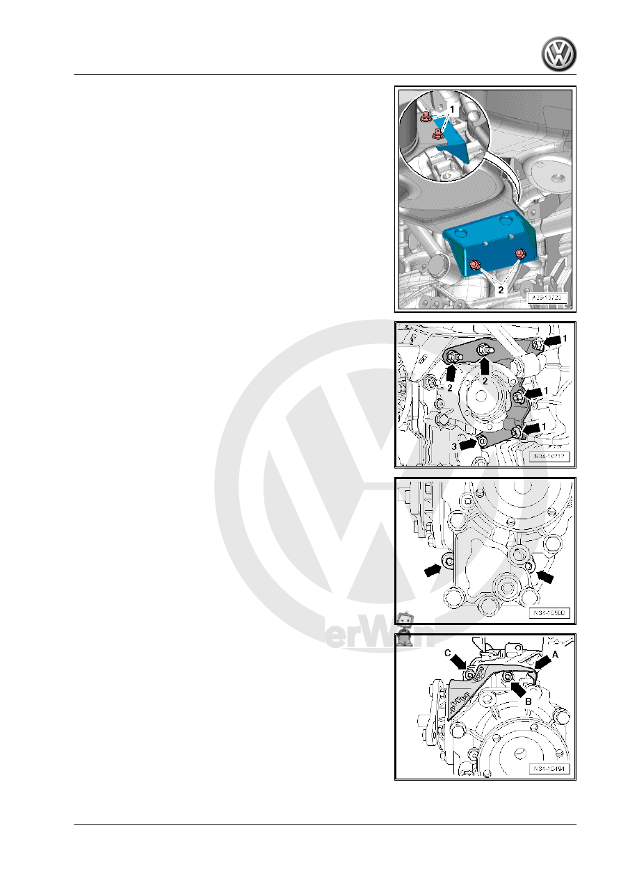
– Remove the transmission mount bolts on the engine and bevel

gear -arrows 1-, -arrows 2- and -arrow 3-.

– Remove the transmission mount.

– Remove the lower bevel gear mounting bolts -arrows- at the

manual transmission.

– Remove upper bevel box mounting bolt at manual transmis‐

sion:

A heat shield -arrow A- is installed on the upper side of the bevel

box on some vehicles.
The bolt -arrow B- is accessible from under the heat shield.
The bolt -arrow C- is accessible from above the heat shield.
– Carefully press bevel box off manual transmission while pro‐

tecting it against falling through.

– Remove bevel box.

9. Bevel Box, Removing and Installing    

207

must be removed.

9.2.2

Bevel Box, Installing

Install in reverse order of removal while. Note the following:
– With the manual transmission installed, lubricate differential

splines with Grease for Clutch Disc Shaft Splines - G 000 100- .

– If the bevel box is being replaced, then install heat shield -A-.
– Tighten the mounting bolts -arrows- to 5 Nm.
– Slide on bevel box completely on manual transmission, while

doing this, join splines of input shaft/bevel box centrally with

differential.

– With proper tooth position and central guiding, bevel box slips

up to stop against manual transmission.

A heat shield -arrow A- is installed on the upper side of the bevel

box on some transmissions.
– Upper bevel box mounting bolts at manual transmission are

accessible as follows:

The bolt -arrow B- is accessible from under the heat shield.
The bolt -arrow C- is accessible from above the heat shield.

Note

Do not pull bevel box with mounting bolts against the transmis‐

sion. Otherwise bevel box is canted and mounting eyelets can

break off.

– Attach the bevel gear transmission mount to the engine and

bevel gear. Follow the tightening sequence when installing the

bolts -arrows 1, 2, and 3-. Refer to

⇒ “9.2.3 Tightening Specifications”, page 210

 .

– Install the EGR cooler (do not open the coolant system) ⇒ 

Rep. Gr.  26 ; EGR System .

208

flange shaft so that the bearing does not get damaged.

– Install flange shaft with a screw and tighten to tightening spec‐

ification -item 13- 

⇒ Item 13 (page 401)

 .

– Install the right drive axle. Refer to ⇒  Suspension, Wheels,

– Attach the right drive axle heat shield to the bevel box

-arrows- and tighten it to the tightening specification. Refer to

⇒ “9.1.3 Tightening Specifications”, page 201

 .

– Install subframe with pendulum support, stabilizer bar, brack‐

ets, steering gear and control arms. Refer to ⇒  Suspension,

Wheels, Steering; Rep. Gr.  40 ; Subframe .

– Attach the driveshaft with the flexible disc to the bevel box

flange -arrows-. Refer to ⇒  Rear Final Drive; Rep. Gr.  39 .

9. Bevel Box, Removing and Installing    

209

The holes for the pendulum support in transmissions from

05/28/2007 have threaded inserts (for example “Heli Coil”).

Characteristic: there is a collar on the first thread -arrow-.

Pay attention to the corresponding bolts and tightening spec‐

40 ; Subframe; Overview - Subframe .

– Attach the pendulum support to the transmission. Refer to ⇒ 

view - Subframe .

– Assemble the exhaust system and then attach the exhaust

– Check the gear oil in the bevel box. Refer to

⇒ “10 Axle Oil in Bevel Box, Checking or Adding”, page 218

 .

– Check transmission fluid level inside the manual transmission.

Refer to 

⇒ “8 Transmission Fluid, Checking”, page 192

 .

50 ; Noise Insulation .

– If equipped, install the breather tube -arrow- in the bevel gear

and tighten to 10 Nm.

If shift mechanism was removed from transmission:

– Attach the cable mounting bracket to the transmission and

tighten the bolts and nuts -arrows- to the tightening specifica‐

tion -item 6- 

⇒ Item 6 (page 86)

 and -item 10-

⇒ Item 10 (page 86)

 .

– Install and adjust shift mechanism. Refer to

⇒ “1.9 Selector Mechanism, Removing and Installing”,

page 92

 .

Diesel Direct Injection System; Air Filter Housing, Removing

and Installing .

– Check the headlamp adjustment if the vehicle has a Left Front

Level Control System Sensor - G78- . Refer to ⇒  Electrical

9.2.3

Tightening Specifications

Bevel box to manual transmission

♦ Replace the bolts.

⇒ Item 17

(page 235)

210


Content   ..  256  257  258  259   ..