Volkswagen Golf Variant / Jetta. Manual - part 239


  Index      Volkswagen     Volkswagen Golf Variant (2007), Jetta (2005) - service repair manual


Search            


Content   ..  237  238  239  240   ..


Volkswagen Golf Variant / Jetta. Manual - part 239


– Remove the pendulum support.

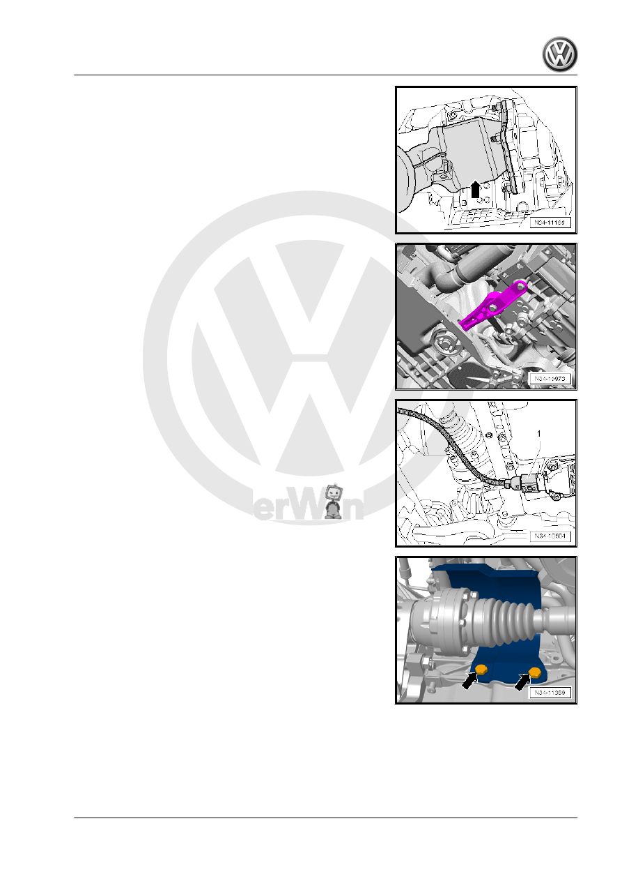
– Disconnect the connector -1- from the Oil Level Thermal Sen‐

sor - G266- .

– Remove the coupling rod from the stabilizer bar and move it

to the side. Refer to⇒  Suspension, Wheels, Steering; Rep.

Gr.  40 .

– Remove the left drive axle. Refer to ⇒  Suspension, Wheels,

– If equipped remove the drive axle heat shield -arrows-. Refer

Overview and Servicing; Drive Axle Heat Shield .

– Remove the right drive axle from the transmission and tie it up.

Axles, Removing and Installing .

3. Transmission, Removing and Installing, Jetta from MY 2005 , Golf Wagon from MY 2007 and Golf Wagon from MY 2010, Vehicles with

Gasoline Engine and FWD    

131

ped.

– Remove the hex collar bolts -arrows- on the left subframe

mount -2- from the left bracket -1-.

– Lower the transmission by adjusting the spindles, which are

attached to the engine, to dimension -a- approximately 40 mm.

Note

When moving the engine/transmission assembly, pay attention to

the connection lines, hoses and radiator.

– Remove the bracket -1- from the transmission -arrows-.

132

then remove the relay lever.

Plastic Relay Lever
– Remove the relay lever with the cable retainer

⇒ “1.8 Plastic Relay Lever”, page 89

 .

Continuation for All
– Remove the gearshift lever from the gearshift shaft.

– Remove the bolt that connects the engine to the transmission

-1-.

Note

Loosen the engine/transmission connecting bolt -3- and leave it

in so that it is hand-tight.

– Tighten the Engine Support Bridge - Gearbox Bracket -

T10346- with the bolt -1- in the left threaded hole in the

subframe.

– Install the Engine Support Bridge - Gearbox Bracket - T10346-

in the same angled position as the engine.

-1- = M6 x 20 collar bolt
– Secure the Engine Support Device - 3300A- on the Engine

Support Bridge - Gearbox Bracket - T10346- .

– Push the engine forward using the spindle on the Engine Sup‐

port Device - 3300A- . Note the following when doing this:

• The A/C compressor -2- must not touch the refrigerant line

-1- -arrow-.

• The generator must not touch the refrigerant line.
• The pressure pipe must not touch the radiator.
Align the Transmission Support - 3282- with the Transmission

Support - Mounting Plate 33 - 3282/33- in order to remove the

“02Q” transmission.
– Insert the Transmission Support - 3282- into the Engine and

Gearbox Jack - VAS6931- .

– Align the arms of the Transmission Support so that they match

up with the holes in the Adjustment Plate .

3. Transmission, Removing and Installing, Jetta from MY 2005 , Golf Wagon from MY 2007 and Golf Wagon from MY 2010, Vehicles with

Gasoline Engine and FWD    

133

ment Plate .

– Install the Transmission Support - Pins 29 - 3282/29- in place

of the Mounting Element -C-.

– Position the Engine-Gearbox Jack - VAG1383 A- under the

vehicle. The arrow symbol -B- on the Adjusting Plate points in

direction of travel.

– Align the Adjusting Plate so that it is parallel to the transmis‐

sion.

– Secure the Slide Hammer Set - Adapter 40 - VW771/40- inside

the threaded hole in the transmission housing as shown.

– Install the Transmission Support - Pins 29 - 3282/29- into the

hole on the transmission for the pendulum support bolt.

– Secure the transmission on the Transmission Support - 3282-

with an M10 x 20 bolt -A-.

The drift -B- must be flush at the bottom with the guide on the

Transmission Support - 3282- -arrow-.
– Remove the connecting bolt -C- and the lower connecting

bolts.

– Separate the transmission from the engine (alignment

sleeves).

The right flange shaft -1- must be guided over the bolting eyelet

of the engine -2-.

Guide the right flange shaft -1- past the flywheel and the opening

-arrow- in the intermediate plate.
– Move the transmission in the area of the differential with the

spindles of the Transmission Support - 3282- into an angled

position.

• The differential, near the transmission, must face upward.
– Guide the transmission and the differential over the subframe

-A- and swing it out.

134


Content   ..  237  238  239  240   ..