Volkswagen Golf Variant / Jetta. Manual - part 200
Adjustment Overview
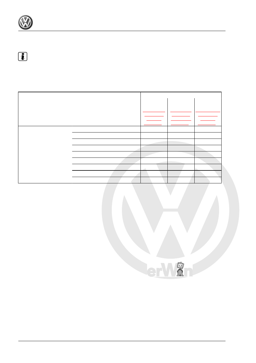
Note
If repairs have been performed on the transmission, it is only nec‐
essary to adjust the input shaft, output shaft or differential if
components have been replaced which have a direct effect on the
adjustment of the transmission. Refer to Table to avoid any un‐
necessary adjusting.
to be adjusted:
Input Shaft
. Refer to
.
Output Shaft
. Refer to
.
Differential
Refer to
.
Replaced part:
Transmission Housing
x
x
Clutch Housing
x
x
x
Input Shaft
x
Output Shaft
x
Differential housing
x
Output shaft tapered roller bearing
x
Output shaft tapered roller bearing
x
Differential tapered roller bearing
x
4th Gear Wheel
x
262