Volkswagen Golf Variant / Jetta. Manual - part 182


  Index      Volkswagen     Volkswagen Golf Variant (2007), Jetta (2005) - service repair manual


Search            


Content   ..  180  181  182  183   ..


Volkswagen Golf Variant / Jetta. Manual - part 182


⇒ Fig. ““Selector Lever/Relay Lever Installed Position”“ , page 76

 .

9 - Cap

❑ For the transmission ventilation

10 - Lock Washer

❑ Always replace.
❑ Not needed for the plastic relay lever

11 - Cap
12 - Spring

❑ Not installed in all transmissions
❑ Install if present

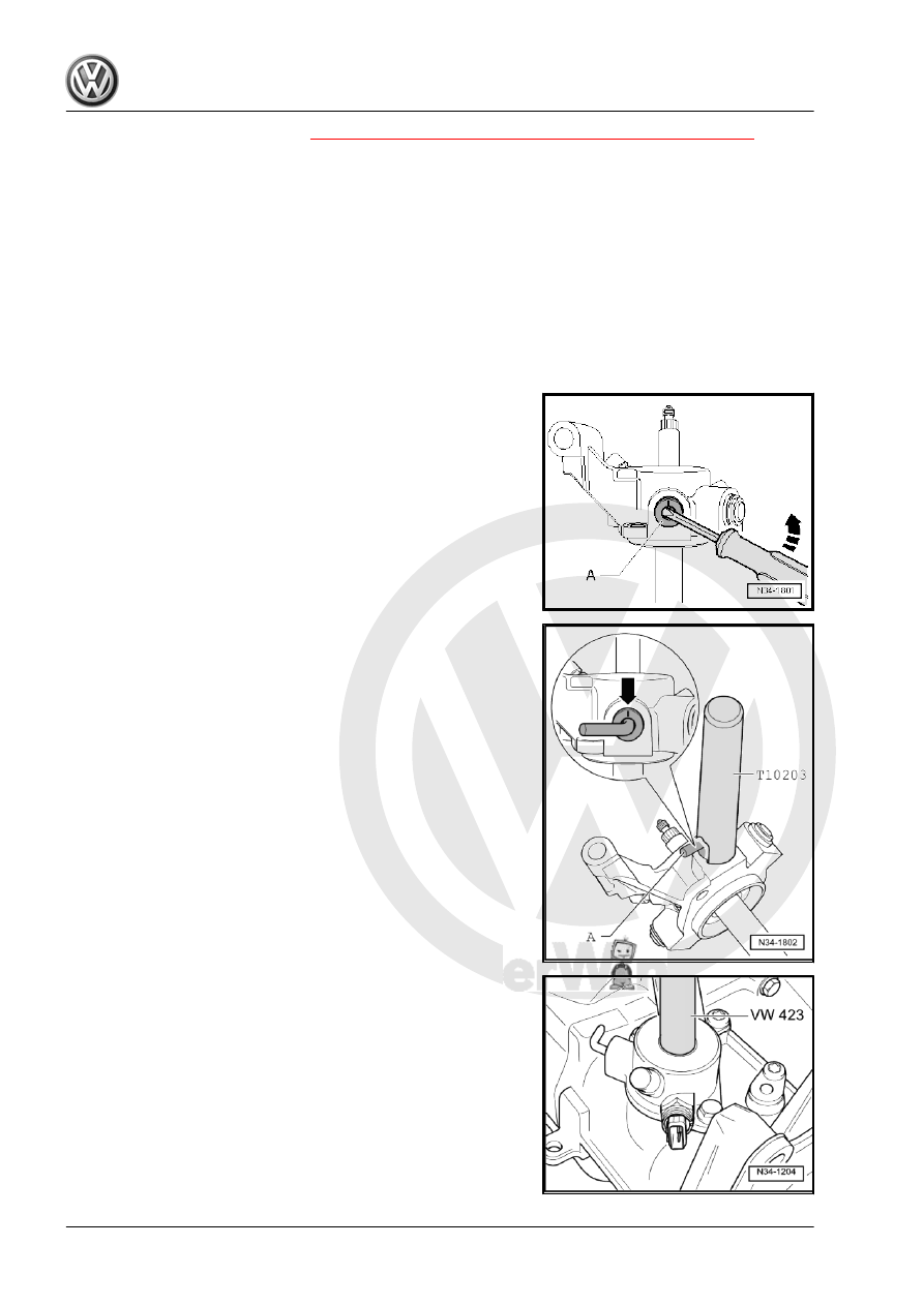
Removing the locking elbow -A- from the shift cover
– Remove the outer part of the locking elbow.
– Remove the locking elbow carefully with a screwdriver.

Pressing the locking elbow -A- into selector cover
Installation position:
The marking -arrow- faces toward upper part of gearshift shaft.

Installing the seal

190

Shift Forks, Disassembling and As‐

sembling

Special tools and workshop equipment required
♦ Press Plate - VW402-
♦ Subframe Support Tool - Press Piece - 3290/1-
♦ Subframe Bushing Tool Kit - 3301-
♦ Press Piece - Multiple Use - VW 431-
♦ Press Piece - Multiple Use Spacer Sleeve - VW 472/2-
♦ Valve Guide/Clutch Release Push Rod Seal Drift - 10 - 206-
♦ Pry Lever - 80-200-
♦ Assembly Mandrel for Gear Selector Rod - 10 - 508-
♦ Spring Strut Compressor - 2070-

Note

The shift fork group (-item 7- 

⇒ Item 7 (page 192)

 ) does not need to be disassembled to remove and install

shift segments, lock washers and angular contact ball bearings.

10. Shift Forks, Disassembling and Assembling    

191

❑ Identification. Refer to

⇒ Fig. ““Shift Segment

Identification”“ ,

page 193

 .

❑ The shift segment must

still rotate easily after

the lock washer is instal‐

led.

2 - Lock Washer

❑ Always replace.
❑ Removing. Refer to

⇒ Fig. ““Removing the

Lock Washer”“ ,

page 193

 .

❑ Installing. Refer to

⇒ Fig. ““Installing the

Lock Washer”“ ,

page 193

 .

3 - 5th Gear Shift Fork

❑ Adjusting. Refer to

⇒ Fig. ““Adjusting the

5th Gear”“ , page 182

 .

4 - Bolt

❑ 25 Nm

5 - 5th Gear Shift Jaw
6 - Angular Contact Ball Bear‐

ing

❑ Quantity: 4
❑ Removing. Refer to

⇒ Fig. ““Removing the

Angular Contact Ball

Bearing”“ , page 193

 .

❑ Installing the bearing in‐

ner race into the outer race. . Refer to

⇒ Fig. ““Installing the angular contact ball bearing inner race -A- into the outer race”“ , page 194

❑ Installing. Refer to 

⇒ Fig. ““Installing the angular contact ball bearing into the shift fork”“ , page 194

 .

7 - Shift Fork Group with Gearshift Rails
8 - 1st/2nd Gear Shift Segment

❑ Identification. Refer to 

⇒ Fig. ““Shift Segment Identification”“ , page 193

 .

❑ The shift segment must still rotate easily after the lock washer is installed.

9 - 3rd/4th Gear Shift Segment

❑ Identification. Refer to 

⇒ Fig. ““Shift Segment Identification”“ , page 193

 .

❑ The shift segment must still rotate easily after the lock washer is installed.

10 - Glide
11 - Spring
12 - Reverse Gear Shift Fork
13 - Support for the reverse gear shift fork
14 - Circlip

192

Removing the Lock Washer
– Secure shift fork in vise with protective jaws -B-.
– Pry off the lock washer -A- in the direction of the -arrow-.

Installing the Lock Washer
– Press the lock washer in the groove in the shift segment using

a socket wrench

Note

The shift segment must still rotate easily after the lock washer is

installed.

A - 10 mm socket wrench
B - Protective Jaws

Removing the Angular Contact Ball Bearing

Note

Be careful not to bend the shift forks when removing and installing

the angular contact ball bearing.

10. Shift Forks, Disassembling and Assembling    

193


Content   ..  180  181  182  183   ..