Volkswagen Golf Variant / Jetta. Manual - part 165


  Index      Volkswagen     Volkswagen Golf Variant (2007), Jetta (2005) - service repair manual


Search            


Content   ..  163  164  165  166   ..


Volkswagen Golf Variant / Jetta. Manual - part 165


retaining brackets.

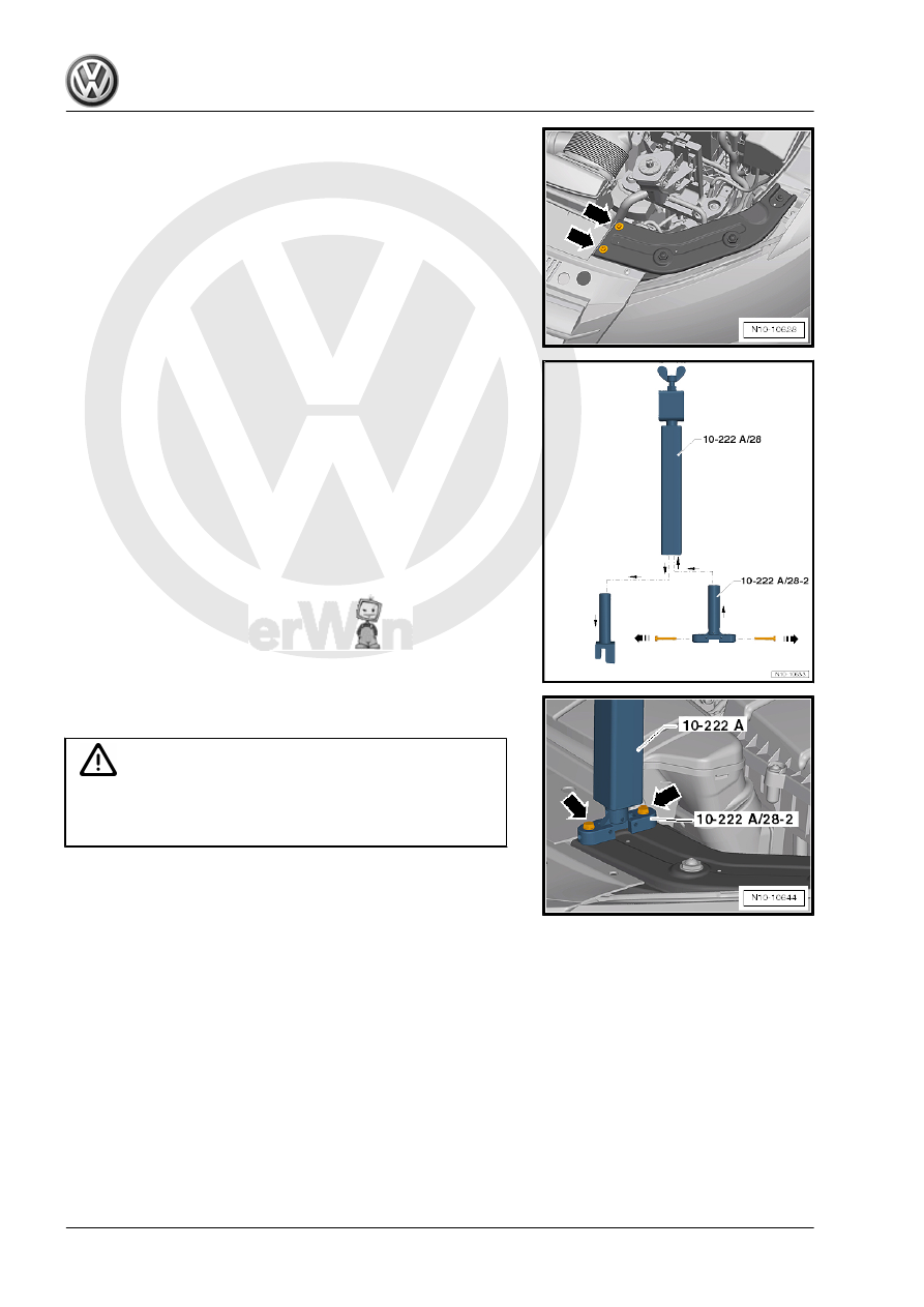
– Remove the lower mounts on the Engine Support Bridge - En‐

gine Support 28 - 10 - 222 A /28- and replace them with the

Engine Support Bridge - Engine Support 28-2 -10-222 A /

28-2- .

– Remove the bolts -arrows- for securing the engine support

bridge on the lock carrier from the Engine Support Bridge -

Engine Support 28-2 - 10-222 A /28-2- .

• Use the bolts in the Engine Support Bridge - Engine Support

28-2 -10 - 222 A /28-2- for attaching the Engine Support Bridge

- Engine Support 28 - 10 - 222 A /28- . Not the bolts for the

retaining bracket.

– Install the Engine Support Bridge - Engine Support 28 - 10 -

222 A /28- and tighten the bolts to 8 Nm -arrows-.

Caution

A second technician is required to mount the Engine Support

Bridge - 10 - 222 A- on the vehicle to prevent the Engine Sup‐

port Bridge from tipping.

122

assembly as follows:
1 - Engine Support Bridge - Engine Support 31 - Adapter 2 - 10

- 222 A /31-2-

2 - Engine Support - Basic Set - Moveable Joint - T40091/3-
3 - Engine Support Bridge - Engine Support 31 - Adapter 1 - 10

- 222 A /31-1-

4 - Engine Support - Supplement Kit - Movable Joint -

T40093/4-

5 - Engine Support - Basic Set - Square Pipe - T40091/1-
6 - Engine Support Bridge - Engine Support 28 - 10 - 222 A /

28- with Engine Support Bridge - Engine Support 28-2

-10-222 A /28-2-

7 - Engine Support - Bracket w/Spindle and Hook - 10 - 222 A /

10-

– First slide the Moveable Joints -2- onto the Square Pipe from

the Engine Support Bridge - 10 - 222 A- .

• The bolts for the Movable Joints - T40091/3- -2- on the Engine

Support Bridge -10-222 A- face the direction of travel.

– Mount the Engine Support Bridge - 10 - 222 A- on the sus‐

pension strut towers and have a second technician hold it to

prevent it from tipping.

– Push the Engine Support - Basic Set - Square Pipe -T40091/1-

-5- from the front left and right through the Engine Support

Bridge - Engine Support 28 -10 - 222 A /28- -6- and place on

each side of the Engine Support - Supplement Kit - Movable

Joint - T40093/4- -4-.

– Additionally attach the Engine Support - Bracket w/Spindle

and Hook - 10 - 222 A /10- -7- on the right Engine Support -

Basic Set - Square Pipe - T40091/1- .

3. Transmission, Removing and Installing, Jetta from MY 2011    

123

T40091/2- -9- with the Engine Support - Supplement Kit -

Mount - T40093/5- -10- in the Engine Support - Supplement

Kit - Movable Joint - T40093/4- -4-.

1 - Engine Support Bridge - Engine Support 31 - Adapter 2 - 10

- 222 A /31-2-

2 - Engine Support - Basic Set - Moveable Joint - T40091/3-
3 - Engine Support Bridge - Engine Support 31 - Adapter 1 - 10

- 222 A /31-1-

4 - Engine Support - Supplement Kit - Movable Joint -

T40093/4-

5 - Engine Support - Basic Set - Square Pipe - T40091/1-
6 - Engine Support Bridge - Engine Support 28 - 10 - 222 A /

28- with Engine Support Bridge - Engine Support 28-2

-10-222 A /28-2-

7 - Engine Support - Bracket w/Spindle and Hook - 10 - 222 A /

10-

8 - Engine Support - Automatic Transmission Hook - 10 - 222

A /7-

9 - Engine Support - Basic Set - Rail with Holes - T40091/2-
10 - Engine Support - Supplement Kit - Mount 5 - T40093/5-
11 - Engine Support Bridge - Spindle - 10 - 222 A /11-
12 - Engine/Gearbox Support Shackle (2 pc.) - 10 - 222 A /12-
– Install the locking pins into the Engine Support - Basic Set -

Rail with Holes - T40091/2- -9- and secure it with the cotter

pins.

– Tighten all the threaded connections on the Engine Support

Bridge hand-tight. While doing so, adjust the height of the En‐

gine Support Bridge parallel over the Engine Support Bridge -

Engine Support 28 - 10 - 222 A /28- .

– Extend the right Engine Support - Bracket w/Spindle and Hook

- 10 - 222 A /10- -7- with the Engine Support - Automatic

Transmission Hook - 10 - 222 A /7- -8-.

The hook on the Engine Support - Automatic Transmission Hook

- 10 - 222 A /7- points downward and will be engaged on cylinder

block later.
– Engage the left Engine Support Bridge - Spindle - 10 - 222 A /

11- -11- in the Engine/Gearbox Support Shackle (2 pc.) - 10 -

222 A /12- -12-.

– Raise the vehicle and remove the left front wheel.
– Remove the noise insulation.
– Remove the left front wheel housing liner. Refer to ⇒  Body

Exterior; Rep. Gr.  66 ; Wheel Housing Liner; Front Wheel

Housing Liner, Removing and Installing .

124

tral Position Sensor - G701- .

Vehicles with Hydraulic Power Steering
– Remove the brackets and the power steering lines from the

transmission -arrows-.

Continuation for all vehicles

– Separate the exhaust system at the double clamp and remove

the front exhaust pipe bracket from the subframe -arrows-.

Caution

Risk of damaging the decoupling element.

♦ Do not bend the decoupling element more than 10°.
♦ Do not load the decoupling element.
♦ Do not damage the wire mesh on the decoupling element.

– Tie up the front exhaust pipe.

– If equipped, remove the heat shield above the right driveshaft

-arrows-.

– Remove the left and right drive axles from the transmission

Gr.  40 ; Drive Axles, Removing and Installing .

3. Transmission, Removing and Installing, Jetta from MY 2011    

125


Content   ..  163  164  165  166   ..