Volkswagen Golf Variant / Jetta. Manual - part 95


  Index      Volkswagen     Volkswagen Golf Variant (2007), Jetta (2005) - service repair manual


Search            


Content   ..  93  94  95  96   ..


Volkswagen Golf Variant / Jetta. Manual - part 95


Torque Converter, Discharging

Special tools and workshop equipment required
♦ Used Oil Collection and Extraction Unit - SMN372500-
Drain the torque converter as follows if the ATF is contaminated:
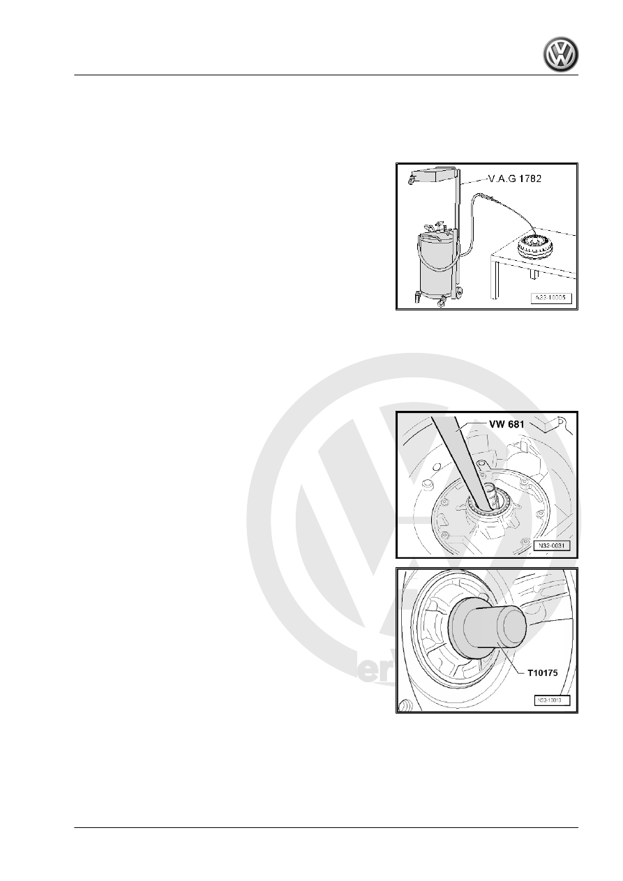
– Extract the ATF from the torque converter using the Used Oil

Collection and Extraction Unit - SMN372500- and the oil ex‐

traction sensor.

1.4

Torque Converter Seal, Removing and

Installing

Special tools and workshop equipment required
♦ Seal Installer - Torque Converter Seal - T10175-
♦ Puller - Seal Lever - VW681-
Removing
– Pry out the seal with the Puller - Seal Lever - VW681- .

Installing
– Coat the outer circumference and the sealing lips on the new

seal with ATF.

• Installation position: open side of the seal toward the trans‐

mission.

– Install the seal using the Seal Installer - Torque Converter Seal

- T10175- until it is flush.

1. Overview - Torque Converter    

11

Special Tools

Special tools and workshop equipment required
♦ Used Oil Collection and Extraction Unit - SMN372500-

♦ Seal Installer - Torque Converter Seal - T10175-

♦ Puller - Seal Lever - VW681-

12

1

»Tester«, Connecting

♦ Vehicle Diagnostic Tester
The operation of these »devices« is described in the respective

owner's manuals.
Connecting the Vehicle Diagnostic Tester to the Data Link Con‐

nector.

WARNING

♦ During a road test, always secure testing and measuring

equipment on the rear seat.

♦ Only a passenger may use the equipment during the road

test.

– Turn on the Vehicle Diagnostic Tester .
The Vehicle Diagnostic Tester is ready for use when it is possible

to select between the fields/buttons 

Guided Functions

 and

Guided Functions

 on the »right« side of the screen.

Depending on equipment and tester version, additional functions

may be »displayed«, for example:

ElsaWin

Measuring Equipment

On Board Diagnostics (OBD)

The »Tester« is Now Ready to be Used.
– Switch the ignition on.
– Touch a field/button on the screen to start desired function.

1. »Tester«, Connecting    

13

Electrical and Electronic Components and Component Locations

1 - Transmission Control Mod‐

ule - J217-

❑ The control module

sends and receives data

from the Data bus.

❑ Component location on

the Jetta from MY 2005,

Bora from 2006, Golf

Wagon from 2007, Jetta

Wagon from 2008. Re‐

fer to

⇒ Fig. ““ Transmission

Control Module -

J217- -arrow- on the Jet‐

ta from MY 2005, the

Bora from MY 2006, the

Golf Wagon from MY

2007 and the Jetta Wag‐

on from MY 2008”“ ,

page 16

❑ Component location on

the Jetta, from MY 2011,

with a 1.8L or 2.0L En‐

gine. Refer to

⇒ Fig. ““ Transmission

Control Module -

J217- -A- on the Jetta

from MY 2011 with 2.0L

- 85 kW and 1.8L - 125

kW Engine”“ ,

page 16

 .

❑ Component location on

the Jetta, from MY 2011,

with a 2.5L - 125 kW en‐

gine. Refer to

⇒ Fig. ““ Transmission

Control Module -

J217- -A- on the Jetta

from MY 2011, with a

2.5L 125 kW Engine”“ ,

page 16

 .

❑ Can be checked in “Guided Fault Finding” using the Vehicle Diagnostic Tester .

2 - Engine Control Module

3 - Multifunction Transmission Range Switch - F125-

❑ Component location. Refer to 

⇒ Fig. ““ Multifunction Transmission Range Switch -F125- ”“ , page 16

❑ Can be checked in “Guided Fault Finding” using the Vehicle Diagnostic Tester .
❑ Removing, installing and adjusting. Refer to

⇒ “3  Multifunction Transmission Range Switch F125 ”, page 20

 .

4 - Valve Body

❑ Component location. Refer to 

⇒ Fig. ““Valve Body”“ , page 17

❑ The components can be checked in “Guided Fault Finding” using the Vehicle Diagnostic Tester .
❑ Allocation. Refer to the Parts Catalog.

5 - Sensor Wiring Harness

❑ 8-pin wiring harness

14


Content   ..  93  94  95  96   ..