Volkswagen Golf Variant / Jetta. Manual - part 67


  Index      Volkswagen     Volkswagen Golf Variant (2007), Jetta (2005) - service repair manual


Search            


Content   ..  65  66  67  68   ..


Volkswagen Golf Variant / Jetta. Manual - part 67


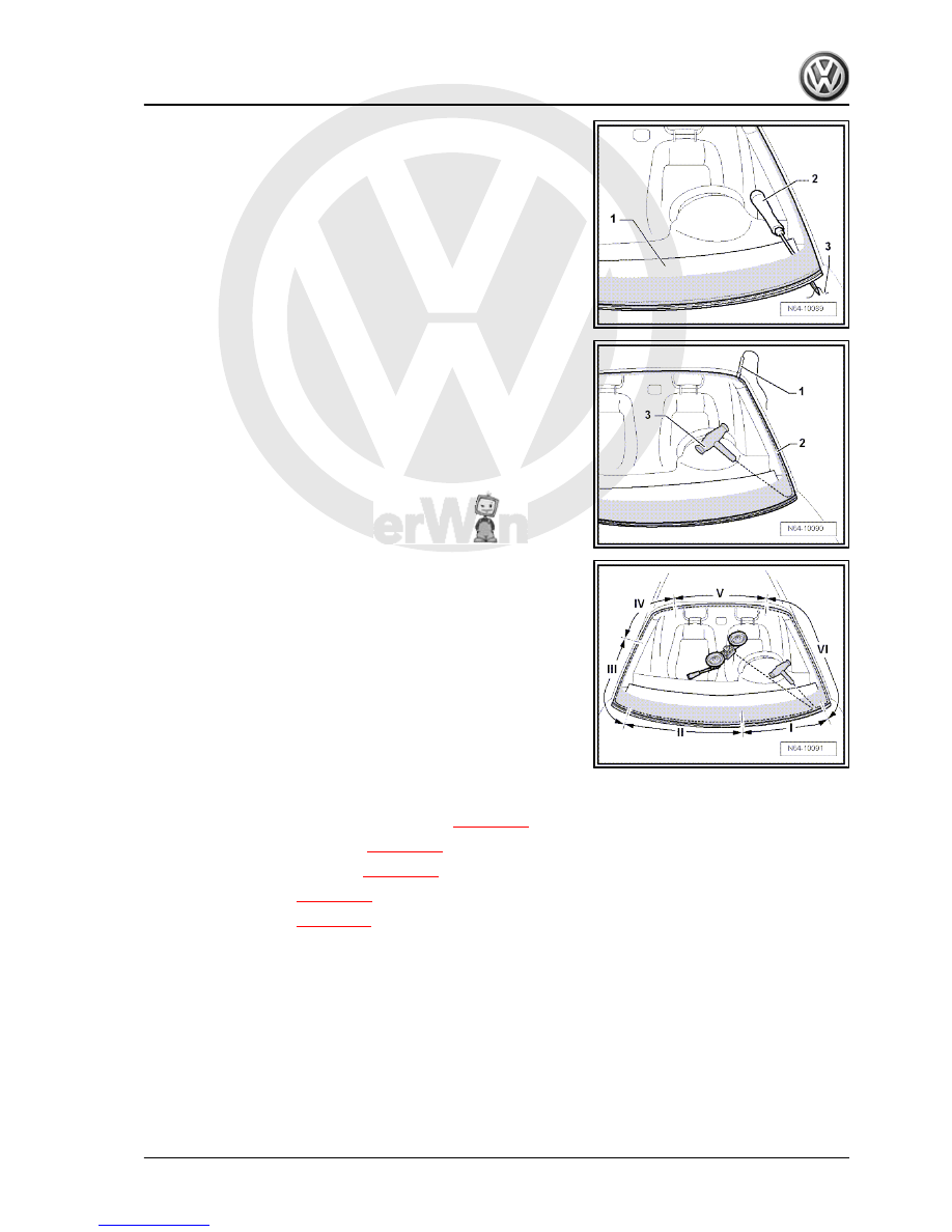
– Thrust awl -V.A.G 1474/2- -2- through adhesive bead.
– Pull cutting cord -3- through adhesive sealing material into in‐

side of vehicle using awl -V.A.G 1474/2- -2-.

– Secure inside end of cutting cord against falling out using pull

handle -V.A.G 1351/1- -3-.

– Place cutting cord -2- using small tube -1- in upper area of

window.

– Lay cutting cord -2- around window and guide second end of

cord inwards into interior.

Ensure that cutting cord -2- lies under window in corners.
– Secure other end of cord to reel device -V.A.G 1654- .

– Position reel device -V.A.G 1654- in “position I”.
– Reposition reel device -V.A.G 1654- as necessary and cut

window free.

– Use wedge -V.A.G 1474/5- to press cutting cord against win‐

dow glass while cutting in order to avoid damaging dash panel

and to create clearance at window flange.

1.6.2

Installing windscreen

Preparing used undamaged window for glazing 

⇒ page 274

Preparing new window for glazing 

⇒ page 274

Preparing body flange for glazing 

⇒ page 275

Installation instructions 

⇒ page 276

 .

Minimum curing period 

⇒ page 276

1. Flush bonded windows    

265


1 - Rear window

❑ Removing and installing

⇒ page 266

2 - Rear lid
3 - PUR adhesive sealant

❑ Cross section of bead:

width = 6.5 mm, height =

10 mm (including resid‐

ual material on window

glass and window

flange).

❑ Minimum curing period

⇒ page 276

4 - Windscreen adjuster
5 - C-pillar trim

❑ Removing ⇒  General

body repairs, interior;

Rep. Gr.  70 ; Pillars and

side panel trim .

1.8

Removing and installing rear window

(saloon)

1.8.1

Removing undamaged rear window

– Remove C-pillar trims ⇒  General body repairs, interior; Rep.

Gr.  70 ; Pillars and side trims .

Gr.  70 ; Roof trims .

70 ; Luggage/load compartment trim .

– Remove high-level brake light ⇒  Electrical system; Rep. Gr. 

94 ; Additional brake lights .

– Disconnect connections for heated rear window and window

aerial.

– Insert cutting cord into window flange using tube.

266


– Pull the other end of the cord through into the interior and

counterhold using handle -V.A.G 1351/1- .

– Secure inner end of cord on reel device -V.A.G 1654- .
– Position reel device -V.A.G 1654- .
– Carefully slide cover -V.A.G 1474/8- -1- between rear window

and moulded headliner, remove moulded headliner securing

screws for this.

– Position reel device -V.A.G 1654- in “position I”.
– Move reel device according to position required and cut win‐

dow free.

– Press cutting thread against window glass with plastic wedge

during cutting process, in order to have clearance at window

flange.

– Instead of reel device -V.A.G 1654- , reel device -V.A.G 1654

A- can be used.

– One suction cup can be removed from the reel device as

shown in illustration. This ensures that the reel device roller

can be guided closer to the window flange.

1.8.2

Removing broken rear window

– Protect body and interior from glass splinters.
– Remove pieces of glass up to adhesive sealing material.
– Remove C-pillar trims ⇒  General body repairs, interior; Rep.

Gr.  70 ; Pillars and side trims .

1. Flush bonded windows    

267


70 ; Luggage/load compartment trim .

– Remove high-level brake light ⇒  Electrical system; Rep. Gr. 

94 ; Additional brake lights .

– Pull off connectors for rear window heating and aerial.
– Cover flange -2- all round with textile-reinforced adhesive

tape.

– Cut through adhesive sealing material (with remains of win‐

dow) in window aperture using electric cutter -V.A.G 1561 A-

and blade -V.A.G 1561/10- (with stop roller).

WARNING

Always wear safety goggles and leather gloves.

1.8.3

Installing rear window

Preparing used undamaged window for glazing 

⇒ page 274

Preparing new window for glazing 

⇒ page 274

Preparing body flange for glazing 

⇒ page 275

Installation instructions 

⇒ page 276

 .

Minimum curing period 

⇒ page 276

268


Content   ..  65  66  67  68   ..