Volkswagen Golf Variant / Jetta. Manual - part 9


  Index      Volkswagen     Volkswagen Golf Variant (2007), Jetta (2005) - service repair manual


Search            


Content   ..  7  8  9  10   ..


Volkswagen Golf Variant / Jetta. Manual - part 9


Note

Vehicle must be standing on the ground to perform the basic

adjustment of the rear lid.

The rear lid lock is bolted directly to the rear lid. It does not

have elongated holes, so it cannot be adjusted.

Adjusting buffers cannot be used to adjust rear lid as they are

in some other vehicles. They have the function of stabilising

and damping the rear lid.

The rear lid adjustment is described step by step below.
Use setting gauge -3371- ⇒ Body Repairs; Rep. Gr.  00 ; Body

dimensions to check or set gap dimensions.
– Remove gas strut 

⇒ page 30

 .

– Adjust rear lid on rear lid hinges by loosening bolts

⇒ Item 9 (page 29)

 .

– Adjust rear lid with rear lid hinges by loosening hexagon nut

⇒ Item 6 (page 29)

 .

– Adjust adjustment buffer 

⇒ page 33

 .

Note

The rear lid is correctly adjusted if, when closed, it is not sunken

or raised, the gap is uniform all around and the contours align.

2.8.1

Adjusting adjustment buffer
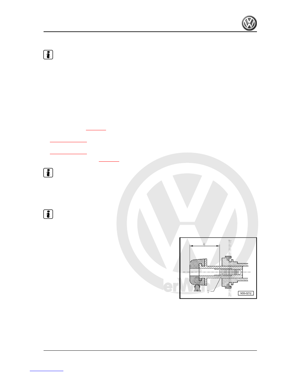
Note

Only the adjustment for the right adjustment buffer is described.

The adjustment for the left adjustment buffer is similar.

– Loosen grub screw -1- until it is visible in rubber buffer.
– Now pull detent slide out of adjustment buffer.

2. Rear lid (saloon)    

33


– Open rear lid again.
– Screw in adjustment buffer clamping screw -1- to a depth of

dimension -a - = 25 mm.

– Check setting.

34


1 - Bowden cable

❑ From lid lock to lock cyl‐

inder

2 - Connector

❑ For bonnet lock

3 - Bowden cable

❑ From lid lock to emer‐

gency release lever in

interior

❑ Only vehicles with

emergency release

from interior

4 - Rear lid trim
5 - Lock cover
6 - Hexagon nut

❑ 8 Nm

7 - Lid lock

❑ Removing and installing

⇒ page 36

8 - Cover

❑ Not supplied with lid lock
❑ Secured on lid lock with

locking lugs

9 - Handle trim

❑ Removing and installing

⇒ page 36

10 - Connector

❑ For registration plate

lighting and release but‐

ton on vehicles with a re‐

lease button

11 - Lock cylinder

❑ Removing and installing 

⇒ page 35

12 - Connector

❑ For lock cylinder

2.10

Removing and installing lock cylinder

2.10.1

Removing

– Removing rear lid trim ⇒  General body repairs, interior; Rep.

Gr.  70 ; Rear lid trim .

2. Rear lid (saloon)    

35


Installing

Install in reverse order of removal.
Specified torque for hexagon nuts: 8 Nm
Before closing rear lid, check function of lid release components.

2.11

Removing and installing handle trim

2.11.1

Removing

– Removing rear lid trim ⇒  General body repairs, interior; Rep.

Gr.  70 ; Rear lid trim .

– Remove lock cylinder 

⇒ page 35

 .

– Disconnect connector -5-.
– Remove nuts -6- and remove handle trim -7-.

2.11.2

Installing

Install in reverse order of removal.
Specified torque for hexagon nuts: 8 Nm
Before closing rear lid, check function of lid release components.

2.12

Removing and installing lid lock

2.12.1

Removing

– Remove lock cover 

⇒ Item 5 (page 35)

 .

– Removing rear lid trim ⇒  General body repairs, interior; Rep.

Gr.  70 ; Rear lid trim .

36


Content   ..  7  8  9  10   ..