Volkswagen Golf / Golf Plus. Manual - part 325
 

  Index      Volkswagen     Volkswagen Golf (2004) / Golf Plus (2005) - service repair manual


Search            


Content   ..  323  324  325  326   ..


Volkswagen Golf / Golf Plus. Manual - part 325


Checking voltage supply of fuel pump -G6- 

⇒ page 138

Checking current consumption of fuel pump -G6- 

⇒ page 139

4.6.1

Test prerequisites

Special tools and workshop equipment required
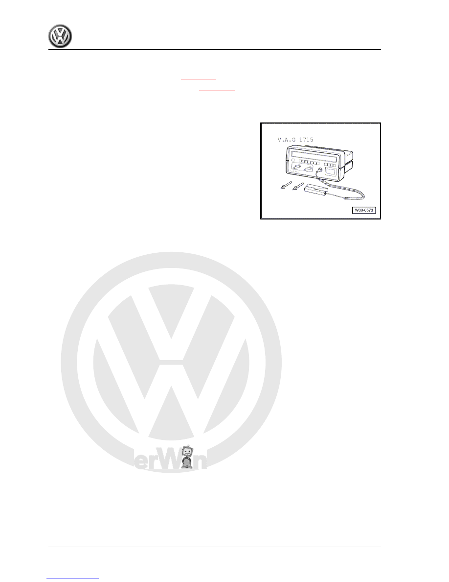
♦ Hand multimeter -V.A.G 1526C- or multimeter -V.A.G 1715-

♦ Auxiliary measuring set -V.A.G 1594 C-
♦ Diode test lamp -V.A.G 1527 B-
• Fuses must be OK.
• The battery voltage must be at least 11.5 V.
• All electrical consumers, e.g. lights and rear window heating,

must be switched off.

4.6.2

Checking function and voltage supply

– Fold rear seats forwards.
– Detach carpet under seats and fold it back. ⇒  General body

repairs, interior; Rep. Gr.  70 ; Load and luggage compartment

trim; Removing and installing luggage compartment floor

– Remove cover from fuel delivery unit.
– Switch on ignition. Fuel pump must be heard to run.
– Switch off ignition.
If the fuel pump does not start:
– Pull 4-pin connector off fuel delivery unit flange.

4-cylinder diesel engine (1.9 l engine) - Edition 01.2009

138

     Rep. Gr.20 - Fuel supply system


-V.A.G 1594 C- .

– Switch on ignition. The LED must light up for about 2 seconds.
If LED does not light up
– Check actuation of fuel pump relay and wiring for open circuit

or short circuit. ⇒ Vehicle diagnosis, testing and information

system VAS 5051

If LED lights up (voltage supply OK):
– Remove fuel delivery unit. 

⇒ page 123

– Check that electrical wiring between flange and fuel pump is

connected and has continuity.

If no open circuit can be found:
– Renew fuel delivery unit. 

⇒ page 123

4.6.3

Checking current draw of fuel pump

– Pull 4-pin connector off fuel delivery unit flange.
– Set multimeter to measuring range 20 A and connect in series

between contacts -1- of connector and fuel pump using auxil‐

iary cables from auxiliary measuring set -V.A.G 1594 C- .

Note

The current pick-up clamp of multimeter -V.A.G 1715- can also

be attached to an auxiliary cable between contacts -1- of con‐

nector and fuel pump.

– Connect contacts -4- of connector and fuel pump using an

auxiliary cable from auxiliary measuring set -V.A.G 1594 C- .

– Start engine and run at idling speed.
– Measure current draw of fuel pump: Specification: max. 7.5

Amperes.

– If the measured value is not within specifications:
– Renew fuel delivery unit. 

⇒ page 123

4-cylinder diesel engine (1.9 l engine) - Edition 01.2009

4. Fuel tank, vehicles with four-wheel drive    

139


Assembly overview - fuel filter 

⇒ page 140

 .

Removing and installing fuel cooler 

⇒ page 141

Assembly overview - accelerator mechanism 

⇒ page 142

 .

Checking tandem pump 

⇒ page 143

Removing and installing tandem pump 

⇒ page 147

5.1

Assembly overview - fuel filter

1 - Supply line

❑ From fuel tank.
❑ White or with white

marking.

❑ Check for secure seat‐

ing.

2 - 8 Nm
3 - Return line

❑ To fuel cooler
❑ Check for secure seat‐

ing.

❑ Blue or with blue mark‐

ing.

4 - Plug for water extraction

❑ Unscrew and drain ap‐

prox. 100 cm

3

 of liquid

using diesel extractor -

VAS 5226-

5 - Seal

❑ Renew.

6 - Supply line

❑ To tandem pump
❑ White or with white

marking.

❑ Check for secure seat‐

ing.

7 - Return line

❑ From tandem pump
❑ Blue marking
❑ Check for secure seat‐

ing.

8 - Fuel filter upper part
9 - Fuel temperature sender -G81-
10 - Seal

❑ Renew.

11 - Filter insert

❑ Observe change intervals.

12 - Seal

❑ Renew.

4-cylinder diesel engine (1.9 l engine) - Edition 01.2009

140

     Rep. Gr.20 - Fuel supply system


17 - Retaining clip

❑ Check for secure seating.

18 - Return line

❑ With connection for fuel temperature sender -G81-

19 - From tandem pump

5.2

Removing and installing fuel cooler

Special tools and workshop equipment required
♦ Torque wrench -V.A.G 1331-

Removing
– Note safety precautions before beginning work 

⇒ page 114

 .

Observe rules for cleanliness 

⇒ page 115

 .

Note

The fuel cooler is located in the return line to fuel tank. It is located

on the vehicle underbody.

– Remove underbody panel.
– Separate fuel lines at fuel cooler.
– Remove securing nuts -arrows-.
Installing
Installation is carried out in the reverse sequence of removal. In

the process, note the following:
♦ Tighten fuel cooler securing nuts to 15 Nm.

4-cylinder diesel engine (1.9 l engine) - Edition 01.2009

5. Repairing fuel supply system    

141


Content   ..  323  324  325  326   ..