Volkswagen Golf / Golf Plus. Manual - part 52


  Index      Volkswagen     Volkswagen Golf (2004) / Golf Plus (2005) - service repair manual


Search            


Content   ..  50  51  52  53   ..


Volkswagen Golf / Golf Plus. Manual - part 52


Special tools and workshop
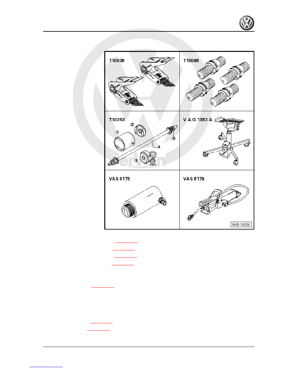
equipment required
♦ Tensioning strap -T10038-
♦ Locating pins -T10096-
♦ Assembly tool -T10263-
♦ Engine and gearbox jack -

V.A.G 1383 A-

♦ Hydraulic press -VAS

6178- and thrust piece -

T10205/13-

♦ Foot pump -VAS 6179-

Pulling out front bonded rubber bush 

⇒ page 205

Pulling in front bonded rubber bush 

⇒ page 207

Pulling out rear bonded rubber bush 

⇒ page 208

Pulling in rear bonded rubber bush 

⇒ page 210

Pulling out front bonded rubber bush
– Remove rear wheels.
– Removing coil spring 

⇒ page 257

 .

– Remove rear exhaust system silencer ⇒  Rep. Gr.  26 ; Ex‐

haust system; Removing and installing parts of the exhaust

system .

– Disconnect electrical connections between rear axle and

body.

– Remove anti-roll bar 

⇒ page 265

 .

– Remove track rods 

⇒ page 231

 .

10. Assembly overview - subframe made from steel, final drive (four-wheel drive)     

205


Do not open brake line.

– Now strap vehicle to the lifting platform arms on both sides of

the vehicle using tensioning straps -T10038- .

WARNING

If the vehicle is not strapped down there is a great danger that

the vehicle will slip off the lifting platform!

– Position engine and gearbox jack -V.A.G 1383 A- with univer‐

sal gearbox support -V.A.G 1359/2- beneath subframe and

secure with strap.

– Unscrew one hexagon bolt -1- or -2- on both sides.

Note

Only the left vehicle side is shown to improve clarity.

To secure the subframe in place, ensure that at positions -1- and

-2- the locating pins -T10096- are screwed in one after the other

on both sides of vehicle.

206

     Rep. Gr.42 - Rear suspension


Note

The locating devices -T10096- must only be tightened to a max‐

imum of 20 Nm; otherwise the threads of the locating pins may

be damaged.

– Replace the subframe securing bolts on both sides one after

the other with locating pins -T10096- and tighten to 20 Nm.

The position of the subframe is now fixed.
– Lower subframe 10 cm using engine and gearbox jack -V.A.G

1383 A- .

– Mark installation position of bonded rubber bush relative to

subframe using e.g. a felt tip pen.

– Position special tools as shown in illustration.
1 - Nut -T10263/5-
2 - Washer , from -T10263-
3 - Tube -T10263/6-
4 - Hydraulic press -VAS 6178- and thrust piece -T10205/13-
5 - Nut -T10263/5-
6 - Spindle -T10263/4-
– Take up play in special tools.
– Pull out bonded rubber bush by actuating the pump.

Note

The outer ring of the bush shears off when pulling out the bonded

rubber bush. This occurs with a loud bang.

– The bonded rubber bush must be removed from the tube -

T10356/6- once the bush has been pulled out.

– Clamp tube -T10356/6- on the intended surfaces in a vice.
– Insert a screwdriver between tube -T10356/6- and bonded

rubber bush and lever bush out of tube -arrow-. If necessary,

apply a drift to bush and drive out with light hammer blows.

Pulling in front bonded rubber bush
Install in reverse order. Note the following points:

10. Assembly overview - subframe made from steel, final drive (four-wheel drive)     

207


parts catalogue “ETKA” .
The bonded rubber bush must be installed in a certain direction;

note mark on subframe.

– Insert bonded rubber bush -1- in subframe so that the nose

and the plate -arrows- face perpendicular to direction of travel.

– Apply thrust piece -T10263/3- -2- so that flattened sides also

face perpendicular to direction of travel.

– Insert special tools with bonded rubber bush into subframe as

shown.

1 - Nut -T10263/5-
2 - Thrust piece -T10263/3-
3 - Bonded rubber bush
4 - Thrust piece -T10263/2-
5 - Hydraulic press -VAS 6178- and thrust piece -T10205/13-
6 - Nut -T10263/5-
7 - Spindle -T10263/4-
– Pre-tension special tools with bonded rubber bush.
– By actuating the pump, carefully draw bonded rubber bush in

until collar lies “flush” on subframe.

– Install track rods 

⇒ page 231

 .

– Install anti-roll bar 

⇒ page 265

 .

– Join electrical connections between rear axle and body.
– Install rear silencer of exhaust system ⇒  Rep. Gr.  26 ; Exhaust

system; Removing and installing parts of the exhaust system .

– Install coil springs 

⇒ page 257

 .

– Fit rear wheels.
Pulling out rear bonded rubber bush
– Remove rear wheels.
– Removing coil spring 

⇒ page 257

 .

– Remove rear exhaust system silencer ⇒  Rep. Gr.  26 ; Ex‐

haust system; Removing and installing parts of the exhaust

system .

208

     Rep. Gr.42 - Rear suspension


Content   ..  50  51  52  53   ..