Volkswagen Golf / Golf Plus. Manual - part 42


  Index      Volkswagen     Volkswagen Golf (2004) / Golf Plus (2005) - service repair manual


Search            


Content   ..  40  41  42  43   ..


Volkswagen Golf / Golf Plus. Manual - part 42


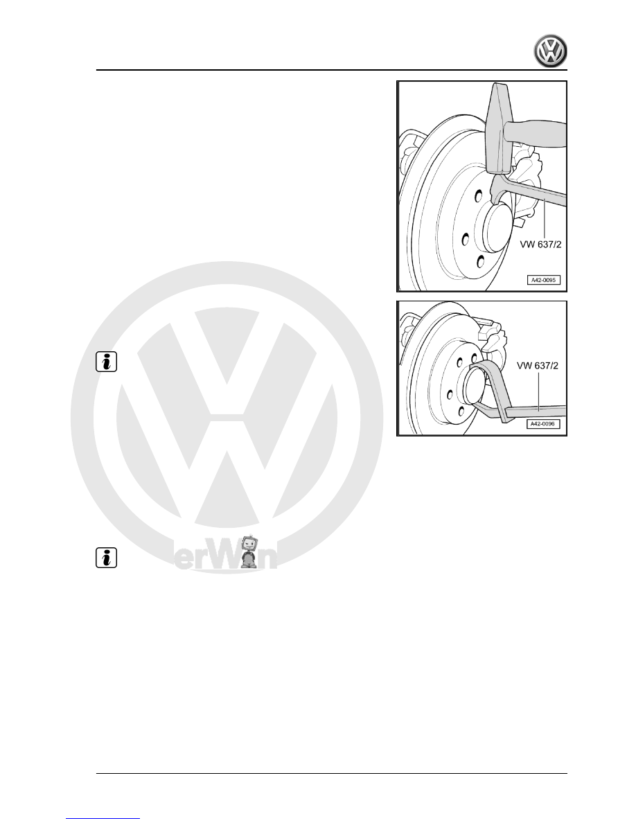
– Lever off grease cap.
– Remove brake carrier with brake caliper and hang from body

with wire ⇒  Brake systems; Rep. Gr.  46 .

Note

Hang brake caliper from body.

– Remove cross-head screw for brake disc and remove brake

disc.

– Remove multi-point socket head bolt using socket insert -

T10162- .

– Pull wheel hub/wheel bearing unit off stub axle.
Installing
– Carefully push wheel bearing/wheel hub unit onto stub axle.
Ensure that the wheel bearing/wheel hub unit does not cant!
– Use a new multi-point socket head bolt and tighten it.

Note

First tighten the bolt to the prescribed torque using a torque

wrench.

Use a rigid spanner to turn bolt further for specified additional

turn.

4. Assembly overview: wheel bearing housing, trailing arm (front-wheel drive)    

165


Always renew removed grease caps.

Damaged grease caps may allow moisture to enter the bear‐

ing. Therefore, always use the tool shown in the illustration.

Continue installation in reverse order.
– Install wheel and tighten bolts or nuts 

⇒ page 288

 .

Specified torques

Component

Specified torque

Wheel hub with wheel bearing to wheel bearing housing

♦ Use new bolt

180 Nm + 180°

Brake disc to wheel bearing housing.

4 Nm

4.4

Removing and installing trailing arm with

mounting bracket

Special tools and workshop equipment required
♦ Torque wrench -V.A.G 1332-

♦ Support -T10149-

Removing
– Remove wheel.
– Remove coil spring 

⇒ page 173

 .

166

     Rep. Gr.42 - Rear suspension


Vehicles with retainer for handbrake cable
– Remove retainer -1- by pushing out inner pin of rivet -arrow-.
Continuation for all vehicles

– Unbolt coupling rod -1- from trailing arm.
– Remove bolts -arrows-.
– Mark installation position of mounting bracket on body.

– Remove bolts -arrows-.
– Remove trailing arm with mounting bracket.
If the trailing arm is to be renewed, the mounting bracket must be

removed from the longitudinal member.
The position of the mounting bracket relative to the trailing arm

must then be adjusted 

⇒ page 167

 .

Determining position of mounting bracket in relation to trailing arm

4. Assembly overview: wheel bearing housing, trailing arm (front-wheel drive)    

167


spring and shock absorber) of respective wheel suspension have

been installed. To tighten, wheel suspension must be in extended

position. Only then do trailing arm and wheel bearing housing

move to the necessary position -arrows-.

Position: threaded connection between trailing arm and wheel

bearing housing
It is important to keep to the specified sequence for the following

operations.

– Position trailing arm and mounting bracket on wheel bearing

housing using bolts -2- but do not tighten yet.

– Attach coupling rod -3- to trailing arm but do not tighten nut

yet.

– Raise wheel suspension using engine and gearbox jack -

V.A.G 1383 A- and support -T10149- until mounting bracket

contacts body.

– Tighten bolts -arrows- on position of old imprint.
– Lower wheel suspension again using engine and gearbox jack

-V.A.G 1383 A- and remove support -T10149- from wheel hub.

168

     Rep. Gr.42 - Rear suspension


Content   ..  40  41  42  43   ..