Toyota FJ Cruiser (GSJ 10, 15 series). Manual - part 36
1GR-FE ENGINE CONTROL SYSTEM – SFI SYSTEM
ES–99
ES
(a) Disconnect the B13 MAF meter connector.
(b) Disconnect the B1 ECM connector.
(c) Check the resistance.
Standard Resistance (Check for open)
Standard Resistance (Check for short)
(d) Reconnect the MAF meter connector.
(e) Reconnect the ECM connector.
NG
OK
4
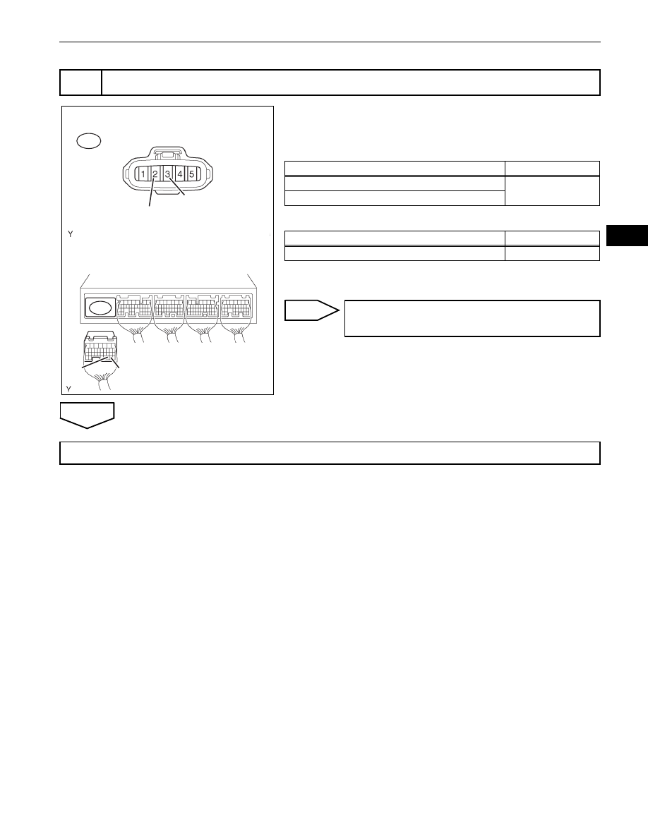
CHECK HARNESS AND CONNECTOR (MASS AIR FLOW METER - ECM)
B1
Wire Harness Side:
ECM Connector
B13
Front View
MAF Meter
Connector
VG
E2G
VG
E2G
A116158E03
Tester Connections
Specified Conditions
VG (B13-3) - VG (B1-30)
Below 1
Ω
E2G (B13-2) - E2G (B1-29)
Tester Connections
Specified Conditions
VG (B13-3) or VG (B1-30) - Body ground
10 k
Ω or higher
REPAIR OR REPLACE HARNESS OR
CONNECTOR
REPLACE MASS AIR FLOW METER (See page
)