Toyota Corolla (2004+). Manual - part 20

32-5
BRAKE
- BRAKE FLUID
(e) Repeat the above procedures to bleed the air out of the
brake line for each wheel.
4.
CHECK FLUID LEVEL IN RESERVOIR
(a) Check the fluid level and add fluid if necessary.
Fluid: SAE J1703 or FMVSS No. 116 DOT3
C80823

32-24
BRAKE
- FRONT BRAKE
FRONT BRAKE
320II-01
COMPONENTS
Union Bolt
29 (296, 21)
Front Disc
Front Disc Brake
F Gasket
Cylinder Sliding Pin
106.8 (1,089, 79)
Flexible Hose
F Bush Dust Boot
106.8 (1,089, 79)
Front Disc Brake
Cylinder Mounting LH
Front Disc
Pad Wear
Brake Cylinder
Indicator Plate
Anti-squeal Shim No.1
Sliding Pin
F Bush Dust Boot
Front Disc Brake Pad Support Plate
Anti-squeal
Pad Wear Indicator
Shim No.2
Plate
Anti-squeal Shim No.2
Disc Brake Pad
Kit Front
Bleeder Plug Cap
Front Disc Brake
34.3 (350, 25)
Pad Support Plate
Disc Brake Pad
Kit Front
Disc Brake Cylinder
Anti-squeal Shim No.1
Bleeder Plug
8.3 (85, 74 in.·lbf)
Assy LH
FCylinder Boot
34.3 (350, 25)
FPiston Seal
FSet Ring
Front Disc Brake Piston
N·m (kgf·cm, ft·lbf)
: Specified torque
F Non-reusable part
Lithium soap base glycol grease
Disc brake grease
F42829

32-25
BRAKE
- FRONT BRAKE
320IJ-01
OVERHAUL
HINT:
Overhaul the RH side by the same procedure as the LH side.
1.
REMOVE FRONT WHEEL
2.
DRAIN BRAKE FLUID
NOTICE:
Wash the brake fluid off immediately if it comes into contact with any painted surface.
3.
REMOVE FRONT DISC BRAKE CYLINDER
SUB-ASSY
(a) Remove the union bolt and gasket from the disc brake cyl-
inder, then disconnect the flexible hose.
HINT:
Gasket has 2 types: 2-piece type and 1-piece type.
C86274
(b) Hold the cylinder slide pin and remove the 2 bolts.
C86275
4.
REMOVE DISC BRAKE PAD KIT FRONT (PAD ONLY)
(a) Remove the 2 brake pads with anti-squeal shims.
(b) Remove the anti-squeal shim No.1 and anti-squeal shim No.2 from each pad.
5.
REMOVE FRONT DISC BRAKE PAD SUPPORT PLATE
(a) Remove the 2 front disc brake pad support plates from the cylinder mounting.
6.
REMOVE FRONT DISC BRAKE CYLINDER SLIDE PIN
(a) Remove the 2 cylinder slide pins from the disc brake cylinder mounting.
7.
REMOVE FRONT DISC BRAKE CYLINDER
MOUNTING LH
(a) Remove the 2 bolts and disc brake cylinder mounting.
F41561

32-26
BRAKE
- FRONT BRAKE
8.
REMOVE FRONT DISC BRAKE BUSH DUST BOOT
(a) Place front disc brake cylinder mounting in vise.
(b) Using a screwdriver and hammer, remove the 2 bush dust
boots from the disc brake cylinder mounting.
C68791
9.
REMOVE CYLINDER BOOT
(a) Using a screwdriver, remove the set ring and cylinder
boot.
R09298
10. REMOVE FRONT DISC BRAKE PISTON
(a) Place a piece of cloth or similar, between the piston and
the disc brake cylinder.
(b) Use compressed air to remove the piston from the disc
brake cylinder.
CAUTION:
Do not place your fingers in front of the piston when using
compressed air.
C64095
NOTICE:
Do not spatter the brake fluid.
11. REMOVE PISTON SEAL
(a) Using a screwdriver, remove the piston seal from the disc brake cylinder.
12. REMOVE FRONT DISC BRAKE BLEEDER PLUG
(a) Remove the bleeder plug cap and bleeder plug from the disc brake cylinder.
13. INSPECT BRAKE CYLINDER AND PISTON
(a) Check the cylinder bore and piston for rust or scoring.
14. INSPECT PAD LINING THICKNESS
(a) Using a ruler, measure the pad lining thickness.
Standard thickness: 11.0 mm (0.433 in.)
Minimum thickness: 1.0 mm (0.039 in.)
R02951

32-27
BRAKE
- FRONT BRAKE
15. INSPECT FRONT DISC BRAKE PAD SUPPORT PLATE
(a) Make sure that they have sufficient rebound, no deformation, cracks or wear, and have had all rust and
dirt cleaned off.
16. INSPECT DISC THICKNESS
(a) Using a micrometer, measure the disc thickness.
Standard thickness: 25.0 mm (0.984 in.)
Minimum thickness: 23.0 mm (0.906 in.)
F42895
17. REMOVE FRONT DISC
Matchmarks
(a) Make matchmarks on the front disc and the axle hub.
(b) Remove the front disc.
18. INSTALL FRONT DISC
(a) Aligning the matchmarks, install the front disc.
HINT:
Select the installation position where the front disc has the mini-
mum runout.
F41543
19. INSPECT DISC RUNOUT
(a) Temporarily fasten the disc with hub nuts.
Torque: 103 N m (1,050 kgf cm, 76 ft lbf)
(b) Using a dial indicator, measure the disc runout 10 mm
(0.39 in.) away from the outer edge of the disc.
Maximum disc runout: 0.05 mm (0.0020 in.)
(c)
If the disc runout is the maximum value or greater, check
the bearing play in the axial direction and check the axle
F42896
hub runout (See page 30-2). If the bearing play and axle
hub runout are normal, adjust the disc runout or grind it
on a ”On-car” brake lathe.
20.
TEMPORARY TIGHTEN FRONT DISC BRAKE BLEEDER PLUG
(a)
Temporarily tighten the bleeder plug, and install bleeder plug cap to the disc brake cylinder.
21.
INSTALL PISTON SEAL
(a)
Apply the lithium soap base glycol grease on a new piston seal.
(b)
Install the piston seal to the disc brake cylinder.
22.
INSTALL FRONT DISC BRAKE PISTON
(a)
Apply the lithium soap base glycol grease on the piston.
(b)
Install the piston to the disc brake cylinder.
NOTICE:
Do not screw the piston forcedly in the disc brake cylinder.

32-28
BRAKE
- FRONT BRAKE
23. INSTALL CYLINDER BOOT
(a) Apply the lithium soap base glycol grease to a new cylin-
der boot. Install the cylinder boot to the disc brake cylin-
der.
HINT:
Install the boot securely to the grooves of the cylinder and pis-
ton.
(b) Using a screwdriver, install the set ring.
F42832
NOTICE:
Do not damage the cylinder boot.
24. INSTALL FRONT DISC BRAKE BUSH DUST BOOT
(a) Place front disc brake cylinder mounting in vise.
(b) Apply the lithium soap base glycol grease to seal surface
of 2 new bush dust boots.
(c)
Using a socket wrench (19 mm) and hammer, drive the 2
bush dust boots to the disc brake cylinder mounting.
C68792
25. INSTALL FRONT DISC BRAKE CYLINDER MOUNTING LH
(a) Install the disc brake cylinder mounting LH with the 2 bolts.
Torque: 106.8 N m (1,089 kgf cm, 79 ft lbf)
26. INSTALL FRONT DISC BRAKE CYLINDER SLIDE PIN
(a) Apply the lithium soap base glycol grease to the sliding part and the seal surface of the 2 cylinder slide
pins.
(b) Install the 2 cylinder slide pins to the disc brake cylinder mounting.
27. INSTALL FRONT DISC BRAKE PAD SUPPORT PLATE
(a) Install the 2 front disc brake pad support plates to the cylinder mounting.
Anti-squeal
28. INSTALL DISC BRAKE PAD KIT FRONT (PAD ONLY)
Front Disc Brake
Shim No.2
Pad Wear Indicator Plate
NOTICE:
If necessary, replace the anti-squeal shim kit when replac-
Anti-squeal
ing the brake pad.
Shim No.1
Anti-squeal
(a) Apply disc brake grease to each anti-squeal shim No.1.
Anti-squeal
Shim No.2
(b) Install anti-squeal shims on each pad.
Shim No.1
(c)
Install the pad wear indicator plate facing upward, and
Disc Brake
install each pad.
Pad Kit
F42831
29. INSTALL FRONT DISC BRAKE CYLINDER SUB-ASSY
(a) Install the disc brake cylinder with the 2 bolts.
Torque: 34.3 N m (350 kgf cm, 25 ft lbf)
C86275

32-29
BRAKE
- FRONT BRAKE
(b) Install a new gasket and flexible hose with the union bolt.
Torque: 29 N m (296 kgf cm, 21 ft lbf)
HINT:
F
Gasket has 2 types: 2-piece type and 1-piece type.
F
Install the flexible hose lock securely in the lock hole in the
disc brake cylinder.
C86274
30. FILL RESERVOIR WITH BRAKE FLUID
31. BLEED MASTER CYLINDER (See page 32-4)
SST
09023-00100
32. BLEED BRAKE LINE (See page
32-4)
33. CHECK FLUID LEVEL IN RESERVOIR
34. CHECK BRAKE FLUID LEAKAGE
35. INSTALL FRONT WHEEL
Torque: 103 N m (1,050 kgf cm, 76 ft lbf)
32-1
BRAKE
- BRAKE SYSTEM
BRAKE SYSTEM
320I7-01
PRECAUTION
F
Care must be taken to replace each part properly, because it could affect the performance of
the brake system and result in a driving hazard. Replace the parts with the parts which have
the same part number or equivalent.
F
It is very important to keep parts and the area clean when repairing the brake system.
F
If the vehicle is equipped with a mobile communication system, refer to the precaution in the
introduction section.

32-38
BRAKE
- PROPORTIONING VALVE ASSY
PROPORTIONING VALVE ASSY
320IM-01
ON-VEHICLE INSPECTION
1.
INSTALL LSPV GAUGE (SST) AND BLEED AIR
(a) Remove the bleeder plugs from the front and rear brake cylinder.
(b) Install the LSPV gauge (SST), and bleed the air.
SST
09709-29018
SST
SST
C86277
2.
RAISE MASTER CYLINDER PRESSURE AND CHECK REAR WHEEL CYLINDER PRESSURE
Master cylinder pressure
Rear wheel cylinder pressure
2,942 kPa (30 kgf/cm2, 427 psi)
2,942 kPa (30 kgf/cm2, 427 psi)
4,903 kPa (50 kgf/cm2, 711 psi)
3,667 kPa (37 kgf/cm2, 531 psi)
7,845 kPa (80 kgf/cm2, 1,138 psi)
4,756 kPa (49 kgf/cm2, 689 psi)
HINT:
When inspecting the fluid pressure, inspect the left front and right rear together, and the right front and left
rear together.
If the rear wheel cylinder pressure is imprper, replace the proportioning valve assy.
3.
REMOVE LSPV GAUGE (SST)
(a) Remove the LSPV gauge (SST).
SST
09709-29018
(b) Install the bleeder plugs.
Torque: 8.3 N m (85 kgf cm, 74 in. lbf)
4.
BLEED MASTER CYLINDER (See page 32-4)
SST
09023-00100
5.
BLEED BRAKE LINE (See page 32-4)
6.
CHECK FOR LEAKS

32-39
BRAKE
- PROPORTIONING VALVE ASSY
320IN-01
REPLACEMENT
1.
REMOVE PROPORTIONING VALVE ASSY
(a) Using SST, disconnect the 5 brake tubes from the propor-
tioning valve assy.
SST
09023-00100
F42835
(b) Remove the 2 bolts and proportioning valve assy from the
body.
F42836
2.
INSTALL PROPORTIONING VALVE ASSY
(a) Install the proportioning valve assy with the 2 bolts.
Torque: 5.4 N m (55 kgf cm, 48 in lbf)
F42836
(b) Using SST, connect the 5 brake tubes to the proportioning
valve assy.
SST
09023-00100
Torque: 15.2 N m (155 kgf cm, 11 ft lbf)
F42835
3.
FILL RESERVOIR WITH BRAKE FLUID
4.
BLEED MASTER CYLINDER (See page 32-4)
SST
09023-00100
5.
BLEED BRAKE LINE (See page 32-4)
6.
CHECK FLUID LEVEL IN RESERVOIR

32-30
BRAKE
- REAR BRAKE
REAR BRAKE
320IK-01
COMPONENTS
Bleeder Plug
10 (102, 7)
8.3 (85, 74 in. lbf)
F
Cylinder
Bleeder Plug Cap
F Cylinder Cup
Dust Boot
15.2 (155, 11)
F Cylinder Cup
Hole Plug
Piston
Pin
F
Cylinder
Pin
Dust Boot
Piston
Compression Spring
Rear Wheel Brake
Cylinder Assy
FC-Washer
Parking Brake Shoe
Lever Sub-assy
Rear Brake Shoe
Return Spring
Parking Brake Shoe
Strut Set LH
Cup
Front Brake Shoe
Shoe Hold-down
Spring
Rear Brake Automatic
Adjust Lever LH
Tension Spring
Shoe Hold-down Spring
Tension Spring
Cup
Parking Brake Shoe
Strut Set LH
Rear Brake Drum Sub-assy
Nm (kgfcm, ftlbf)
: Specified torque
F Non-reusable part
Lithium soap base glycol grease
High temperature grease
F42669

32-31
BRAKE
- REAR BRAKE
320IL-01
OVERHAUL
HINT:
Overhaul the RH side by the same procedures with LH side.
1.
REMOVE REAR WHEEL
2.
DRAIN BRAKE FLUID
NOTICE:
Wash the brake fluid off immediately if it comes into contact with any painted surface.
3.
REMOVE REAR BRAKE DRUM SUB-ASSY
(a) Release the parking brake lever, and remove the brake
Contract
drum.
HINT:
If the brake drum cannot be removed easily, do the following
steps.
(b) Remove the hole plug and insert a screwdriver through
the hole in the backing plate, and hold the automatic ad-
F42837
justing lever away from the adjuster.
(c)
Using a another screwdriver, reduce the brake shoe ad-
juster by turning the adjusting wheel.
4.
INSPECT BRAKE DRUM INSIDE DIAMETER
(a) Using a brake drum gauge or equivalent, measure the in-
side diameter of the drum.
Standard inside diameter: 200.0 mm (7.874 in.)
Maximum inside diameter: 201.0 mm (7.913 in.)
F06408
5.
REMOVE REAR BRAKE AUTOMA TIC ADJUST LEVER
LH
(a) Using a needle-nose pliers, remove the upper side ten-
sion spring.
(b) Remove the rear brake automatic adjust lever LH from the
rear brake shoe.
F42670

32-32
BRAKE
- REAR BRAKE
6.
REMOVE FRONT BRAKE SHOE
(a) Using a needle-nose pliers, remove the anchor side ten-
sion spring.
F42671
(b) Using SST, remove the cup, shoe hold-down spring and
pin.
SST
09718-00010
(c)
Disconnect the upper side return spring from the front
SST
brake shoe, and remove the front brake shoe.
F42672
7.
REMOVE PARKING BRAKE SHOE STRUT SET LH
8.
REMOVE REAR BRAKE SHOE
(a) Using SST, remove the cup, shoe hold-down spring and
pin.
SST
09718-00010
SST
F42673
(b) Using a needle-nose pliers, disconnect the parking brake
cable No.3 and remove the rear brake shoe.
(c)
Remove the upper side return spring from the rear brake
shoe.
F42688

32-33
BRAKE
- REAR BRAKE
9.
REMOVE REAR BRAKE PARKING BRAKE SHOE
LEVER SUB-ASSY
(a) Using a screwdriver, remove the C-washer and parking
brake shoe lever.
F42689
10. INSPECT REAR DRUM B RAKE SHOE LINING
THICKNESS
(a) Using a ruler, measure the thickness of the shoe lining.
Standard thickness: 4.4 mm (0.173 in.)
Minimum thickness: 1.0 mm (0.039 in.)
If the lining thickness is at the minimum thickness or less, or if
there is severe, uneven wear, replace the brake shoe.
F42690
11. INSPECT BRAKE DRUM AND REAR DRUM BRAKE
SHOE LINING FOR PROPER CONTACT
(a) Apply chalk to the inside surface of the drum, then grind
drum on the brake shoe lining to fit.
If the contact between the drum and the shoe lining is improper,
repair it using a brake shoe grinder or replace the brake shoe
assembly.
R01564
12. REMOVE RH, FRONT OR UPPER REAR WHEEL
BRAKE CYLINDER ASSY
(a) Using SST, disconnect the brake tube, use a container to
catch brake fluid.
SST
09023-00100
(b) Remove the bolt and wheel cylinder.
F42691
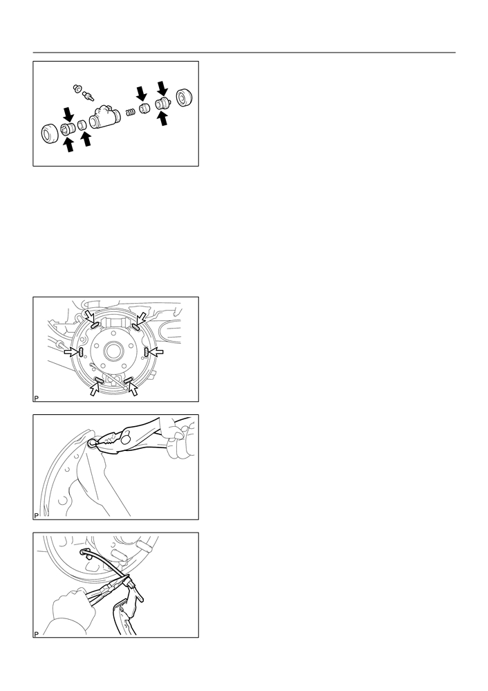
13. REMOVE REAR WHEEL CYLINDER CUP KIT
(a) Remove the 2 cylinder dust boots from the wheel cylinder.
(b) Remove the 2 pistons and compression spring.
(c)
Remove the 2 wheel cylinder cups from each piston.
(d) Remove the bleeder plug cap and bleeder plug from the wheel cylinder.
14. INSPECT BRAKE WHEEL CYLINDER
(a) Check the cylinder bore and piston for rust or scoring.
32-34
BRAKE
- REAR BRAKE
15. INSTALL REAR WHEEL CYLINDER CUP KIT
(a) Temporary tighten the bleeder plug to the wheel cylinder,
and install the bleeder plug cap.
(b) Apply the lithium soap base glycol grease to 2 new wheel
cylinder cups and the 2 pistons.
(c)
Install the 2 wheel cylinder cups to each piston.
(d) Install the compression spring and 2 pistons to the wheel
cylinder.
F42692
(e) Install 2 new cylinder dust boots to the wheel cylinder.
16. INSTALL RH, FRONT OR UPPER REAR WHEEL BRAKE CYLINDER ASSY
(a) Install the wheel cylinder with the bolt.
Torque: 10 N m (102 kgf cm, 7 ft lbf)
(b) Using SST, connect the brake tube.
SST
09023-00100
Torque: 15.2 N m (155 kgf cm, 11 ft lbf)
17. APPLICATION HIGH TEMPERATURE GREASE
(a) Apply the high temperature grease to the shoe attached
surface of backing plate.
F42693
F42893
18. INSTALL REAR BRAKE PARKING BRAKE SHOE
LEVER SUB-ASSY
(a) Using a pliers, install the parking brake shoe lever with a
new C-washer.
F42694
19. INSTALL REAR BRAKE SHOE
(a) Using a needle-nose pliers, connect the parking brake
cable No.3 to the parking brake shoe lever.
F42688