Subaru Tribeca (2014 year). Manual - part 15


  Index      Subaru     Subaru Tribeca - service manual 2014 year in english


Search            


Content   ..  13  14  15  16   ..


Subaru Tribeca (2014 year). Manual - part 15


especially metal ones such as

coins or aluminum foil, into the

accessory power outlet. That

could cause a short circuit. Al-

ways put the cap on the acces-

sory power outlet when it is not

in use.

. Use only electrical appliances

which are designed for 12V DC.
The maximum power rating of an

appliance that can be connected

is shown in the following list. Do

not use an appliance which ex-

ceeds the indicated wattage for

each outlet.
– The two outlets in the center

console: 120W or less (When

using appliances connected

to two outlets simultaneously,

the total power consumed by

them must not exceed 120W.)

– The two outlets in the rear

cabin: 120W or less (When

using appliances connected

to two outlets simultaneously,

the total power consumed by

them must not exceed 120W.)

Overloading the accessory

power outlet can cause a short

circuit. Do not use dual adapters

or more than one electrical appli-

ance.

. If the plug on your electric appli-

ance is either too loose or too

tight for the accessory power

outlet, this can result in a poor

contact or cause the plug to get

stuck. Only use plugs that fit

properly.

. Use of an electric appliance in the

accessory power outlet for a long

period of time while the engine is

not running can cause battery

discharge.

. Before driving your vehicle, make

sure that the plug and the cord

on your electrical appliance will

not interfere with your shifting

gears and operating the accel-

erator and brake pedals. If they

do, do not use the electrical

appliance while driving.
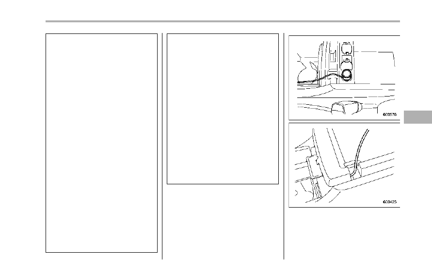
NOTE

It is possible, when using the outlet in

the center console (lower compart-

ment) with the lid closed, to pass the

electrical appliance’s cord through a

gap between the center console (lower

Interior equipment

6-11

– CONTINUED –

6-12

Interior equipment

compartment) and the lid. It is also

possible to pass the cord through a

groove in the lid and up to the center

console (upper compartment).

Coat hook

A coat hook is attached to each hand grip

for the outboard second-row passenger’s

seats.

WARNING

Do not hang coat hangers or other

hard or pointed objects on the coat

hooks. If such items were hanging

on the coat hooks during deploy-

ment of the SRS curtain airbags,

they could cause serious injuries by

coming off the coat hooks and being

thrown through the cabin or by

preventing correct airbag deploy-

ment. Before hanging clothing on

the coat hooks, make sure there are

no pointed objects in the pockets.

Hang clothing directly on the coat

hooks without using hangers.

CAUTION

Never hang anything on the coat

hook that might obstruct the driver’s

view or that could cause injury in

sudden stops or in a collision. And

do not hang items on the coat hook

that weigh 11 lbs (5 kg) or more.

Shopping bag hook

CAUTION

Do not hang items on the shopping

bag hook that weigh 11 lbs (5 kg) or

more.

A shopping bag hook is attached to each

side of the cargo area.

Floor mat

A retaining pin is located on the driver’s

side of the vehicle next to the fuel filler

door release. Fit the grommet in the carpet

onto the pin to prevent the carpet from

moving.

CAUTION

If the floor mat slips forward and

interferes with the movement of the

pedals during driving, it could cause

an accident. Observe the following

precautions to prevent the floor mat

from slipping forward.
. Be sure to use a genuine

SUBARU floor mat designed with

grommets in the correct loca-

tions.

. Make sure that the driver’s floor

mat is placed back in its proper

location and is correctly secured

on its retaining pins.

Interior equipment

6-13

– CONTINUED –

6-14

Interior equipment

. Do not use more than one floor

mat.

Cargo area cover (if

equipped)

The cargo area cover is provided for

covering the cargo area and to protect its

contents from direct sunlight. This cover is

detachable to make room for additional

cargo.

& Using the cover

1)

Holder

1. Insert the seatbelt webbing into the

holder of the third-row seat.
2. Fold down the seatback of the third-

row seat. Refer to “Folding down the

seatback” F1-15.

3. To extend the cover, pull the end of the

cover out of the housing, then insert its

hooks into the catches as shown. To

rewind it, unhook it from the catches and

it will rewind automatically. You should

hold on to the cover and guide it back into

the cover housing while it is rewinding.

WARNING

Do not place anything on the ex-

tended cover. Putting excessive

weight on the extended cover can

break it and an object on the cover

could tumble forward in the event of

a sudden stop or collision. This

could cause serious injury.

CAUTION

. Be careful not to pinch your hand

between the headrest and the

cargo area cover when you re-

cline the second-row seat.

. Be careful not to scratch the rear

gate stays while extending and

rewinding the cover.
Scratches on the stays could

cause leakage of gas from the

stays, which may result in their

inability to hold the rear gate

open.

NOTE

When the head restraint is adjusted at

the rearmost position of the seat with

the seatback leaned back, the head

restraint comes in contact with the

cargo area cover. In this case, raise

the seatback before adjusting the head

restraint.
If the head restraint is correctly fixed in

any of the lock positions, the head

restraint does not contact the cargo

area cover even when the seatback is

reclined.

& To remove the cover

1. Rewind the cover.

2. Pull either sleeve on the end of the

cover housing to shorten the cover’s

length.
3. Take it off the retainer.

& To install the cover housing

1. Remove the cover at the cover hous-

ing retaining part using a flat-head screw-

driver.
2. Pull either sleeve on the end of the

cover housing to shorten the cover’s

length.

Interior equipment

6-15

– CONTINUED –

6-16

Interior equipment

3. Insert the projections located on the

both ends of the sleeve into the recesses

of the retainers.

Convenient tie-down hooks

CAUTION

The convenient tie-down hooks are

designed only for securing light

cargo. Never try to secure cargo

that exceeds the capacity of the

hooks. The maximum load capacity

is 44 lbs (20 kg) per hook.

The cargo area is equipped with four tie-

down hooks so that cargo can be secured

with a luggage net or ropes.

When using the tie-down hooks, turn them

down out of the storing recesses. When

not in use, put the hooks up into the

storing recesses.

Under-floor storage compart-

ment

The subfloor storage compartment is

located under the floor of the cargo area

and can be used to store small items. To

open the lid, pull the handle up.

CAUTION

. Always keep the lid of the sub-

floor storage compartment

closed while driving to reduce

the risk of injury in the event of

sudden stop or an accident.

. Do not store spray cans, contain-

ers with flammable or corrosive

liquids or any other dangerous

items in the subfloor storage

compartment.

Hang the hook provided on the underside

of the lid on the rear edge of the roof to

keep the lid open.

HomeLink

®

Wireless Control

System (if equipped)

1)

HomeLink

®

buttons

2)

Indicator light

3)

Hand-held transmitter*

* Not part of your vehicle’s remote

keyless entry system but of a

HomeLink

®

-compatible device.

The HomeLink

®

Wireless Control System,

located on the driver’s sun visor, is a

handy way to operate, from inside of your

vehicle, up to three remote-controlled

indoor and outdoor devices, such as

garage door openers, entrance gates,

door locks, home lighting, and security

systems. There are three HomeLink

®

buttons on the sun visor, each of which

you can program for operation of one

desired device. For details on the device

types which can be operated by this

system, consult the HomeLink website at

www.homelink.com or call 1-800-355-

3515.

Note the following about this system:
If your vehicle is equipped with the

HomeLink

®

Wireless Control System, it

complies with Part 15 of the Federal

Communication Commission Rules in the

U.S. and the RSS-210 of Industry Canada

in Canada. Its operation is subject to the

following two conditions:
(1) this device may not cause harmful

interference, and (2) this device must

accept any interference received, includ-

ing interference that may cause undesired

operation.

Changes and modifications to this system

by anyone other than an authorized

service facility could void authorization to

use this equipment.

HomeLink and the HomeLink house are

registered trademarks of Johnson Con-

trols, Inc.

WARNING

. W h e n p r o g r a m m i n g t h e

HomeLink

®

Wireless Control Sys-

tem, you may be operating a

Interior equipment

6-17

– CONTINUED –

6-18

Interior equipment

garage door opener or other

device. Make sure that people

and objects are out of the way

of the garage door opener or

other device to prevent potential

harm or damage.

. Do not use the HomeLink

®

Wire-

less Control System with any

garage door opener that lacks

the safety stop and reverse fea-

ture as required by applicable

safety standards. A garage door

opener which cannot detect an

object, signaling the door to stop

and reverse, does not meet these

safety standards. Using a garage

door opener without these fea-

tures increases risk of serious

injury or death. For more infor-

mation, consult the HomeLink

website at www.homelink.com

or call 1-800-355-3515.

CAUTION

When programming the HomeLink

®

Wireless Control System to operate

a garage door opener or an entrance

gate, unplug the device’s motor

from the outlet during programming

to prevent motor burnout.

NOTE

. After programming your HomeLink

®

Wireless Control System for the de-

sired devices, retain the hand-held

transmitters for further programming

or device testing in the event of a

problem.
. It is recommended that you insert a

new battery in the hand-held transmit-

ter of a device to ensure correct

programming.

& Garage door opener pro-

gramming in the U.S.A.

NOTE

When programming the HomeLink

®

Wireless Control System for a garage

door opener, it is suggested that you

park the vehicle outside the garage.
1. Unplug the motor of the garage door

opener from the outlet.

NOTE

When reprogramming any of the

HomeLink

®

buttons that are already

programmed for other devices, perform

the procedure in step 2.

2. Press and hold the two outside

HomeLink

®

buttons until the indicator light

begins to flash (after 10 seconds). Re-

lease both buttons.
3. Hold the end of the garage door

opener’s hand-held transmitter between

1 and 3 inches (25 and 76 mm) away from

the HomeLink

®

buttons on the driver’s sun

visor, keeping the indicator light in view.

4. Using both hands, simultaneously

push the hand-held transmitter button

and the desired HomeLink

®

button. DO

NOT release the buttons until step 5 has

been completed.
5. Hold down both buttons until the

HomeLink

®

indicator light flashes, first

slowly then rapidly. When the indicator

light flashes rapidly, both buttons may be

released. (The rapidly flashing light indi-

cates successful programming of the new

frequency signal.)
6. Press and hold the programmed but-

ton and check the HomeLink

®

indicator

light. If the indicator light stays on con-

tinuously, your garage door should acti-

vate and the programming is completed.
If the indicator light flashes rapidly for 2

seconds and then stays on continuously,

your garage door opener may be pro-

tected by a rolling code feature. In this

case you need to perform additional steps.

Refer to “Programming rolling-code-pro-

tected garage door openers in the U.S.A.”

F6-19.

NOTE

Rolling-code-protected garage door

openers are manufactured after 1996.

See the instruction manual of your

garage opener for confirmation.
7. Reconnect the motor of your garage

door opener to the outlet.
8. Test your garage door opener by

pressing the programmed HomeLink

®

but-

ton.

& Programming rolling-code-

protected garage door open-

ers in the U.S.A.

If your garage door opener has a rolling

code feature, program the HomeLink

®

Wireless Control System for it by following

steps 1 through 5 in “Garage door opener

programming in the U.S.A.” F6-18 above.

Then continue with the following steps.

NOTE

The assistance of a second person

may make the programming quicker

and easier.

1. Locate the training button on the

garage door opener motor head unit.

The exact location and color of the button

may vary by brand of garage door opener.

If it is difficult to locate the training button,

refer to your garage door opener’s instruc-

tion manual.

Interior equipment

6-19

– CONTINUED –

6-20

Interior equipment

1)

Training button

2. Press the training button on the

garage door opener motor head unit

(which activates the “training light” on the

unit). Proceed to step 3 within 30 seconds.
3. Inside the vehicle, firmly press and

release the HomeLink

®

button that was

programmed in the section above. Press

and release the button a second time to

complete the programming procedure.

NOTE

Some garage door openers may re-

quire you to do the above procedure a

third time to complete the program-

ming.
4. The garage door opener should now

recognize the HomeLink

®

Wireless Control

System and your garage door opener

should activate when the HomeLink

®

button is pressed.

& Programming for entrance

gates and garage door open-

ers in Canada

1. Unplug the motor of the entrance gate

or garage door opener from the outlet.

2. Press and hold the two outside buttons

until the HomeLink

®

indicator light begins

to flash (after 10 seconds). Release both

buttons.

NOTE

When reprogramming any of the

HomeLink

®

buttons that are already

programmed for other devices, perform

the procedure in step 2.
3. Hold the end of the entrance gate’s/

garage door opener’s hand-held transmit-

ter between 1 and 3 inches (25 and 76

mm) away from the HomeLink

®

buttons on

the driver’s sun visor, keeping the indica-

tor light in view.

4. Press and hold the desired HomeLink

®

button.
5. Press and release (“cycle”) the hand-

held transmitter button every 2 seconds

until step 6 is complete.
6. When the indicator light flashes slowly

and then rapidly after several seconds,

release both buttons.
7. Plug the motor of the entrance gate/

garage door opener to the outlet.
8. Test your entrance gate/garage door

opener by pressing the programmed

HomeLink

®

button.

& Programming other devices

To program other devices such as door

locks, home lighting and security systems,

contact HomeLink at www.homelink.com

or call 1-800-355-3515.

& Operating the HomeLink

®

Wireless Control System

Once programmed, the HomeLink

®

Wire-

less Control System can be used to

remote-control the devices to which its

buttons are programmed. To activate a

device, simply press the appropriate but-

ton. The indicator light illuminates, indicat-

ing that the signal is being transmitted.

& Erasing HomeLink

®

button

memory

NOTE

. Performing this procedure erases

the memory of all the preprogrammed

buttons simultaneously. The memory

of individual buttons cannot be erased.
. It is recommended that upon the

sale of the vehicle, the memory of all

programmed HomeLink

®

buttons be

erased for security purposes.

1. Press and hold the two outside buttons

until the indicator light begins to flash

(after 10 seconds).

2. Release both buttons.

& In case a problem occurs

If you cannot activate a device using the

corresponding HomeLink

®

button after

programming, contact HomeLink at

www.homelink.com or call 1-800-355-

3515 for assistance.

Rear view camera (if

equipped)

A rear view camera is attached to the rear

gate. When the ignition switch is “ON” and

the select lever is set to “R”, the rear view

camera automatically displays the rear

view image behind the vehicle on the

navigation monitor or on the inside mirror.

WARNING

. Since the rear view camera uses

a wide-angle lens, the image on

the monitor is different from the

actual view in terms of distance.

. Since the range of the image on

the monitor is limited, you should

always check the rear view and

Interior equipment

6-21

– CONTINUED –

6-22

Interior equipment

the surrounding area with your

eyes and mirrors, and move

backward at a slow speed. Mov-

ing backward only by checking

the rear view image from the

camera could cause an accident.

. Do not disassemble or modify the

camera, switch or wiring. If

smoke comes out or you smell

a strange odor, stop using the

rear view camera immediately.

Contact your SUBARU dealer

for an inspection. Continued use

may result in accident, fire or

electric shock.

CAUTION

. If your vehicle is washed with a

high-pressure washer, do not

allow water to contact the camera

directly. Entry of water in the

camera lens may result in con-

densation, malfunction, fire or

electric shock.

. Since the camera is a precision

device, do not subject it to strong

impacts. Otherwise, malfunction,

fire or electric shock may occur.

. If mud or snow sticks to or is

frozen on the camera, you must

be very careful removing it.

Otherwise, damage done to the

camera may cause a fire or

electric shock. Pour water or

lukewarm water over the camera

to remove mud and ice, and wipe

it with a soft, dry cloth.

. Do not put a flame close to the

camera or wiring. Otherwise, da-

mage or fire may occur.

. When replacing the fuse, be sure

to use a fuse with the specified

rating. Use of a fuse with a

different rating may result in a

malfunction.

. If the rear view camera is used for

a long time while the engine is

not operated, the battery may

become completely discharged.

NOTE

. Do not wipe the camera with alcohol,

benzine or paint thinner. Otherwise,

discoloration may occur. To remove

contamination, wipe the camera with a

cloth moistened with a diluted neutral

detergent and then wipe it with a soft,

dry cloth.
. When waxing the vehicle, be careful

not to apply the wax to the camera. If it

comes in contact with the camera,

moisten a clean cloth with a diluted

neutral detergent to remove the wax.
. The camera lens has hard coating to

help prevent scratches. However, when

washing the vehicle or cleaning the

camera lens, be careful not to scratch

the camera lens. Do not use a washing

brush directly on the camera lens. The

monitor screen may be adversely af-

fected.
. Strong light shined on the camera

lens may develop white light stripes

around the light source. This is not a

malfunction.
. Under the fluorescent light, the dis-

play may flicker. However, this is not a

malfunction.
. The image of the rear view camera

may be slightly different from the

actual color of the objects.

& How to use the rear view

camera

When the select lever is set to “R”, the rear

view camera automatically displays the

rear view image from the vehicle. When

the lever is set to other positions, the

image before setting to “R” is displayed.
1. Set the ignition switch to “ON”.
2. Set the select lever to “R”.

NOTE

. The image of the rear view camera

has priority over other screen displays.
. The image of the rear view camera is

horizontally reversed as is the case

with the vehicle rearview mirror or the

side view mirror.
. It may be difficult to see the image of

the rearview camera in the following

cases. This is not a malfunction of the

camera.

– The vehicle is in a dark place (at

night, in a tunnel, etc.).
– The vehicle is in an extremely hot

or cold place.
– An object (such as raindrops,

snow, dirt, etc.) that disturbs the

view of the rear view camera sticks

to the lens of the camera.
– Strong light shined directly on

the camera lens (occasionally, there

are vertical lines on the screen).

& Viewing range on the screen

Range of view

Range of view

Image from camera

The area from the rear end of the bumper

can be viewed. Areas at both ends of the

bumper and areas just under the bumper

cannot be viewed.
Also, the image from the rear view camera

looks shorter than the actual distance.

CAUTION

The range that can be viewed with

the rear view camera is limited.

Always be sure to check with your

eyes when moving backward and

proceed slowly.

Interior equipment

6-23

– CONTINUED –

6-24

Interior equipment

Range of view

Image from camera

The area above the camera cannot be

viewed. If there is an object that has a

wide projection on its upper part such as a

sign pole behind the vehicle, the projec-

tion cannot be seen on the screen.

CAUTION

The range that can be viewed with

the rear view camera is limited.

Always be sure to check with your

eyes when moving backward and

proceed slowly.

& Help line

The help line (distance marker and vehicle

width line) is a guide to help you realize

the actual distance from the screen.

Help lines displayed on the navigation

monitor

Help lines displayed on the inside mirror
1)

Vehicle width line (oblique vertical line)

2)

Approx. 10 feet (3 m) from the bumper

(green horizontal line)

3)

Approx. 6.5 feet (2 m) from the bumper

(green horizontal line)

4)

Approx. 3 feet (1 m) from the bumper

(yellow horizontal line)

5)

Approx. 1.5 feet (0.5 m) from the bumper

(red horizontal line)

When the select lever is set to position
“R”, the monitor screen displays the help

lines together with the rear view image.

CAUTION

. When moving backward, always

check the back with your eyes

without relying on the help lines.

. The actual position may be dif-

ferent from the indication of the

help lines.

. Differences may occur due to

number of passengers or loaded

cargo.

. When the vehicle is on a slope or

when the vehicle is inclined

against the road, the indication

is different from the actual posi-

tion.

! Difference between screen and ac-

tual road

The distance markers show the distance

for a level road when the vehicle is not

loaded. It may be different from the actual

distance depending on the loading condi-

tions or road conditions.

! When there is an upward slope at

the back

1)

3 feet (1 m)

The distance on the screen looks farther

than the actual distance.

! When there is a downward slope

at the back

1)

3 feet (1 m)

The distance on the screen looks nearer

than the actual distance.

NOTE

When cargo is loaded, the rear view

distance on the screen looks farther

than the actual distance as in an

upward slope.

Interior equipment

6-25

– CONTINUED –

6-26

Interior equipment

! Feature of distance marker

1)

3 feet (1 m) line

2)

6.5 feet (2 m) line

3)

10 feet (3 m) line

The distance marker shows the distance

on the road. If there is a car or other object

close behind, distance cannot be correctly

displayed.


Content   ..  13  14  15  16   ..