Subaru Legacy IV (2008 year). Service manual - part 915


  Index      Subaru     Subaru Legacy IV - service and repair manual 2008 year


Search            


Content   ..  913  914  915  916   ..


Subaru Legacy IV (2008 year). Service manual - part 915


ABS(diag)-59

Diagnostic Procedure with Diagnostic Trouble Code (DTC)

ABS (DIAGNOSTICS)

Y: DTC C0119 G SENSOR OUTPUT SIGNAL MALFUNCTION

DTC DETECTING CONDITION:
Defective G sensor
TROUBLE SYMPTOM:
ABS does not operate.
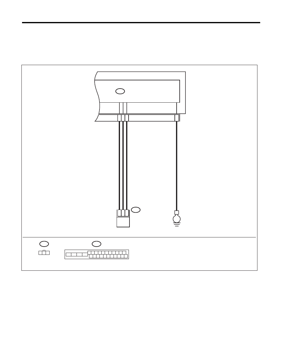
WIRING DIAGRAM:

ABS00808

ABSCM & H/U

B301

B301

10

24

21

15

B292

ABS G SENSOR

E

3

2

1

B292

1 2 3

1 2 3 4 5 6 7 8 9 10 11

16 17 18 19 20 21 22 23 24 25 26

13

12

15

14

ABS(diag)-60

Diagnostic Procedure with Diagnostic Trouble Code (DTC)

ABS (DIAGNOSTICS)

Step

Check

Yes

No

1

WHETHER A WHEEL TURNED FREELY OR 
NOT.

Have the wheels spun free of 
load when the vehicle is lifted 
up, or during driving on a rough 
road?

ABS is normal. 
Clear the memory.

Go to step 2.

2

CHECK OUTPUT OF G SENSOR USING 
SUBARU SELECT MONITOR.
1) Select {Current Data Display & Save} in the 
Subaru Select Monitor.
2) Read the Subaru Select Monitor display.

Is the reading indicated on dis-
play –1.2 — 1.2 m/s when the G 
sensor is horizontal?

Go to step 3.

Go to step 8.

3

CHECK OUTPUT OF G SENSOR USING 
SUBARU SELECT MONITOR.
1) Turn the ignition switch to OFF.
2) Remove the console box.
3) Remove the G sensor from vehicle. (Do not 
disconnect the connector.)
4) Turn the ignition switch to ON.
5) Select {Current Data Display & Save} in the 
Subaru Select Monitor.
6) Read the Subaru Select Monitor display.

Is the value indicated on the 
screen 8.1 — 11.2 m/s when G 
sensor is inclined forward to 
90°?

Go to step 4.

Replace the G sen-
sor. <Ref. to ABS-
18, G Sensor.>

4

CHECK OUTPUT OF G SENSOR USING 
SUBARU SELECT MONITOR.
Read the Subaru Select Monitor display.

Is the value indicated on the 
screen –8.1 — –11.2 m/s when 
G sensor is inclined backward 
to 90°?

Go to step 5.

Replace the G sen-
sor. <Ref. to ABS-
18, G Sensor.>

5

CHECK POOR CONTACT IN CONNECTOR.
Turn the ignition switch to OFF.

Is there poor contact in connec-
tors between ABSCM&H/U and 
G sensor?

Repair the connec-
tor.

Go to step 6.

6

CHECK ABSCM&H/U.
1) Connect all connectors.
2) Clear the memory. <Ref. to ABS(diag)-20, 
Clear Memory Mode.>
3) Perform the Inspection Mode. <Ref. to 
ABS(diag)-19, Inspection Mode.>
4) Read the DTC.

Is the same DTC displayed?

Replace the 
ABSCM only. <Ref. 
to ABS-8, 
REPLACEMENT, 
ABS Control Mod-
ule and Hydraulic 
Control Unit 
(ABSCM&H/U).>

Go to step 7.

7

CHECK FOR ANY OTHER DTC ON DISPLAY. Is any other DTC displayed?

Check DTC using 
“List of Diagnostic 
Trouble Code 
(DTC)”. <Ref. to 
ABS(diag)-29, List 
of Diagnostic Trou-
ble Code (DTC).>

Temporary poor 
contact occurs.

8

CHECK OPEN CIRCUIT IN G SENSOR OUT-
PUT HARNESS AND GROUND HARNESS.
1) Turn the ignition switch to OFF.
2) Disconnect the ABSCM&H/U connectors.
3) Measure the resistance between 
ABSCM&H/U connector terminals.

Connector & terminal

(B301) No. 21 — No. 10:

Is the resistance 3.6 — 3.8 k

:? Go to step 9.

Repair the harness 
connector between 
the G sensor and 
ABSCM&H/U.

9

CHECK GROUND SHORT OF HARNESS.
Measure the resistance between the 
ABSCM&H/U connector and chassis ground.

Connector & terminal

(B301) No. 21 — Chassis ground:

Is the resistance 1 M

: or 

more?

Go to step 10.

Repair the harness 
connector between 
the G sensor and 
ABSCM&H/U.

ABS(diag)-61

Diagnostic Procedure with Diagnostic Trouble Code (DTC)

ABS (DIAGNOSTICS)

10

CHECK G SENSOR.
1) Remove the console box.
2) Remove the G sensor from vehicle.
3) Connect the connector to G sensor.
4) Connect the connector to ABSCM&H/U.
5) Turn the ignition switch to ON.
6) Measure the voltage between G sensor 
connector terminals.

Connector & terminal

(B292) No. 2 (+) — No. 3 (–):

Is the voltage 2.1 — 2.5 V when 
G sensor is in horizontal posi-
tion?

Go to step 11.

Replace the G sen-
sor. <Ref. to ABS-
18, G Sensor.>

11

CHECK G SENSOR.
Measure the voltage between G sensor con-
nector terminals.

Connector & terminal

(B292) No. 2 (+) — No. 3 (–):

Is the voltage 3.6 — 4.1 V when 
the G sensor is inclined forward 
to 90°?

Go to step 12.

Replace the G sen-
sor. <Ref. to ABS-
18, G Sensor.>

12

CHECK G SENSOR.
Measure the voltage between G sensor con-
nector terminals.

Connector & terminal

(B292) No. 2 (+) — No. 3 (–):

Is the voltage 0.5 — 1.0 V when 
G sensor is inclined back 90°?

Go to step 13.

Replace the G sen-
sor. <Ref. to ABS-
18, G Sensor.>

13

CHECK ABSCM&H/U.
1) Turn the ignition switch to OFF.
2) Connect all connectors.
3) Clear the memory. <Ref. to ABS(diag)-20, 
Clear Memory Mode.>
4) Perform the Inspection Mode. <Ref. to 
ABS(diag)-19, Inspection Mode.>
5) Read the DTC.

Is the same DTC displayed?

Replace the 
ABSCM only. <Ref. 
to ABS-8, 
REPLACEMENT, 
ABS Control Mod-
ule and Hydraulic 
Control Unit 
(ABSCM&H/U).>

Go to step 14.

14

CHECK FOR ANY OTHER DTC ON DISPLAY. Is any other DTC displayed?

Check DTC using 
“List of Diagnostic 
Trouble Code 
(DTC)”. <Ref. to 
ABS(diag)-29, List 
of Diagnostic Trou-
ble Code (DTC).>

Temporary poor 
contact occurs.

Step

Check

Yes

No

ABS(diag)-62

General Diagnostic Table

ABS (DIAGNOSTICS)

13.General Diagnostic Table

A: INSPECTION

Symptom

Problem parts

Vehicle instability during braking

Vehicle is pulled to either right or 
left side.

• ABSCM&H/U (solenoid valve)
• ABS wheel speed sensor
• Brake (caliper, piston and pad)
• Wheel alignment
• Tire specifications, tire wear and air pressures
• Incorrect wiring or piping connections
• Road surface (uneven, camber)

Vehicle spins.

• ABSCM&H/U (solenoid valve)
• ABS wheel speed sensor
• Brake (pad)
• Tire specifications, tire wear and air pressures
• Incorrect wiring or piping connections

Poor brake performance

Long braking/stopping distance

• ABSCM&H/U (solenoid valve)
• Brake (pad)
• Air in brake line
• Tire specifications, tire wear and air pressures
• Incorrect wiring or piping connections

Wheel locks.

• ABSCM&H/U (solenoid valve, motor)
• ABS wheel speed sensor
• Incorrect wiring or piping connections

Brake drag

• ABSCM&H/U (solenoid valve)
• ABS wheel speed sensor
• Master cylinder
• Brake (caliper and piston)
• Parking brake
• Axle & wheels
• Brake pedal play

Long brake pedal stroke

• Air in brake line
• Brake pedal play

Vehicle vertical pitching

• Suspension play or fatigue (reduced damping)
• Incorrect wiring or piping connections
• Road surface (uneven)

Unstable or uneven braking

• ABSCM&H/U (solenoid valve)
• ABS wheel speed sensor
• Brake (caliper, piston and pad)
• Tire specifications, tire wear and air pressures
• Incorrect wiring or piping connections
• Road surface (uneven)

Vibration and/or noise
(while driving on slippery roads)

Excessive pedal vibration

• Incorrect wiring or piping connections
• Road surface (uneven)

Noise from the ABSCM&H/U

• ABSCM&H/U (mount bushing)
• ABS wheel speed sensor
• Brake line

Noise from front of vehicle

• ABSCM&H/U (mount bushing)
• ABS wheel speed sensor
• Master cylinder
• Brake (caliper, piston, pad and rotor)
• Brake line
• Brake booster and check valve
• Suspension play or fatigue

Noise from rear of vehicle

• ABS wheel speed sensor
• Brake (caliper, piston, pad and rotor)
• Parking brake
• Brake line
• Suspension play or fatigue


Content   ..  913  914  915  916   ..