Subaru Legacy IV (2008 year). Service manual - part 737
 

  Index      Subaru     Subaru Legacy IV - service and repair manual 2008 year


Search            


Content   ..  735  736  737  738   ..


Subaru Legacy IV (2008 year). Service manual - part 737


5AT-72

Transfer Clutch

AUTOMATIC TRANSMISSION

4) Calculation formula:
When clearances are 0.2 mm (0.008 in):
T (mm) = A – B + 0.08
[T (in) = A – B + 0.0031]
When clearances are 0.6 mm (0.024 in):
T (mm) = A – B – 0.32
[T (in) = A – B – 0.0126]
T: Thickness of driven plate No. 3
A: Depth from mating surface of extension case to
multi-plate clutch (LSD) piston
B: Height from AT main case mating surface to end
of ST

Standard:

0.2 — 0.6 mm (0.008 — 0.024 in)

NOTE:
Calculation formula for “T” is applied when measur-
ing using ST (398643600 GAUGE, 398744300
PISTON GUIDE). When not using the ST,
When clearances are 0.2 mm (0.008 in):
T (mm) = A – (B – 

D – 0.28) – 0.2

[T (in) = A – (B – 

D – 0.011) – 0.008]

When clearances are 0.6 mm (0.024 in):
T (mm) = A – (B – 

D – 0.28) – 0.6

[T (in) = A – (B – 

D – 0.011) – 0.024]

is applied.
T: Thickness of driven plate No. 3
A: Depth from mating surface of extension case to
multi-plate clutch (LSD) piston
B: Height from the AT main case mating surface to
the contact face of the tool that was used as the
substitute of the ST.
D: Thickness of tool used when measuring “B”
0.28 (0.011): Gasket thickness (Unit mm (in))
If it is out of specification, select the driven plate No.
3 to adjust within the specification.

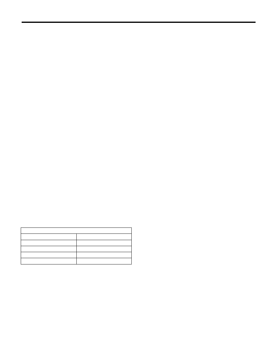
Driven plate No. 3

Part No.

Thickness mm (in)

31589AA041

1.6 (0.063)

31589AA050

2.0 (0.079)

31589AA060

2.4 (0.094)

31589AA070

2.8 (0.110)

5AT-73

Rear Drive Shaft

AUTOMATIC TRANSMISSION

27.Rear Drive Shaft

A: REMOVAL

1) Remove the transmission assembly from vehicle
body. <Ref. to 5AT-39, REMOVAL, Automatic
Transmission Assembly.>
2) Remove the rear vehicle speed sensor, and then
remove the extension case. <Ref. to 5AT-68, RE-
MOVAL, Extension Case.>
3) Pull out the rear driveshaft from center differen-
tial assembly.

4) Remove the drive plate and driven plate.

B: INSTALLATION

1) Select shims. <Ref. to 5AT-70, ADJUSTMENT,
Transfer Clutch.>
2) Install the drive plate and driven plate.
3) Insert the rear driveshaft into the center differen-
tial assembly.
4) Combine the extension case, and then install the
rear vehicle speed sensor. <Ref. to 5AT-68, IN-
STALLATION, Extension Case.>
5) Install the transmission assembly to the vehicle.
<Ref. to 5AT-43, INSTALLATION, Automatic
Transmission Assembly.>

C: DISASSEMBLY

1) Using a press, remove the revolution gear.

2) Using a press, remove the front and rear side
ball bearings and clutch hub.

D: ASSEMBLY

Assemble in the reverse order of disassembly.

NOTE:
• Use new ball bearings and revolution gear.
• Make sure the clutch hub is facing the correct di-
rection.

E: INSPECTION

• Check each parts for holes, damages or other
foreign matters.
• Inspect the extension end play, and adjust it to
within the standard value. <Ref. to 5AT-70, AD-
JUSTMENT, Transfer Clutch.>

(A) Revolution gear

AT-03231

AT-00149

(A)

(A) Rear ball bearing

(B) Rear drive shaft

(C) Clutch hub

(A) Front side

(B) Clutch hub

(C) Rear side

(D) Revolution gear

AT-00151

(A)

(B)

(C)

AT-00152

(A)

(B)

(C)

(D)

5AT-74

Reduction Driven Gear

AUTOMATIC TRANSMISSION

28.Reduction Driven Gear

A: REMOVAL

1) Remove the transmission assembly from vehicle
body. <Ref. to 5AT-39, REMOVAL, Automatic
Transmission Assembly.>
2) Remove the rear vehicle speed sensor, and sep-
arate the extension case from transmission case.
<Ref. to 5AT-68, REMOVAL, Extension Case.>
3) Remove the center differential carrier. <Ref. to
5AT-77, REMOVAL, Center Differential Carrier.>
4) Set the range select lever to the “P” range.
5) Using ST1, ST2 and ST3, pull out the reduction
driven gear.
ST1

499737100

PULLER SET

ST2

18680AA010

GEAR HOLDER

ST3

18766AA000

SUPPORT PULLER

B: INSTALLATION

1) Set the range select lever to the “P” range.
2) Use a plastic hammer to install reduction driven
gear assembly.
3) Select the reduction gear shims. <Ref. to 5AT-
76, ADJUSTMENT, Reduction Driven Gear.>
4) Join the transmission case and the extension
case, and then install the rear vehicle speed sen-
sor. <Ref. to 5AT-68, INSTALLATION, Extension
Case.>
5) Install the transmission assembly to the vehicle.
<Ref. to 5AT-43, INSTALLATION, Automatic
Transmission Assembly.>

C: DISASSEMBLY

1) Remove the ball bearing from reduction driven
gear using ST.
ST

498077300

REMOVER

2) Remove the ball bearing on the reverse side with
the same procedure as step 1).
ST

498077300

REMOVER

3) Remove the snap ring of the parking gear.

(A) Reduction driven gear

AT-03271

ST2

ST1

ST2

ST3

(A)

(A) Ball bearing

(A) Ball bearing

AT-00157

(A)

ST

AT-01969

(A)

ST

AT-03264

5AT-75

Reduction Driven Gear

AUTOMATIC TRANSMISSION

4) Using the ST, remove the parking gear.
ST

18767AA000

REMOVER

D: ASSEMBLY

1) Using the ST, install the parking gear.
ST

499755602

PRESS

2) Install the snap ring.

3) Install the new ball bearing to reduction driven
gear using press.
ST

18654AA000

INSTALLER

4) Install the ball bearing on the reverse side with
the same procedure as step 3).
ST

18654AA000

INSTALLER

AT-03265

ST

AT-03266

ST

AT-03264

AT-03267

ST

AT-03268

ST


Content   ..  735  736  737  738   ..