Subaru Legacy IV (2008 year). Service manual - part 673
4AT-40
Automatic Transmission Assembly
AUTOMATIC TRANSMISSION
23) Insert the front drive shaft into the transmission
securely by pressing the front housing from the out-
side.
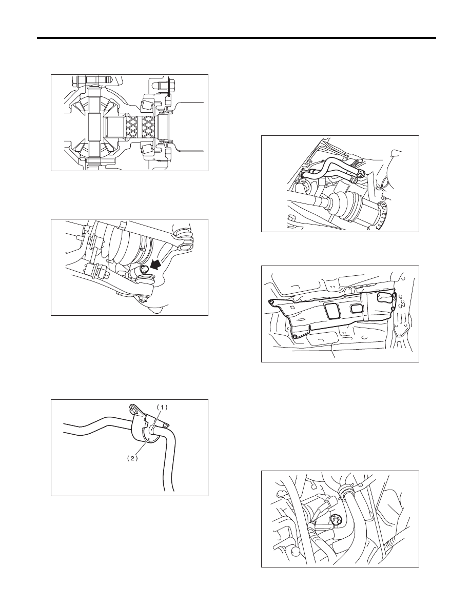
24) Install the ball joint into the housing.
25) Tighten the attachment bolts.
Tightening torque:
50 N·m (5.1 kgf-m, 36.9 ft-lb)
26) Install the stabilizer to the front crossmember.
NOTE:
• Install the bushing (on front crossmember side)
while aligning it with the paint mark on the stabiliz-
er.
• Make sure the bushing and stabilizer are marked
with the same identification colors (paint mark)
when installing.
27) Always tighten the rubber bushing locations
with wheels in full contact with the ground and the
vehicle at curb weight.
Tightening torque:
25 N·m (2.5 kgf-m, 18.4 ft-lb)
28) Install the shift select cable onto select lever.
<Ref. to CS-30, INSTALLATION, Select Cable.>
29) Install the oil charge pipe, and connect the ATF
cooler hoses to the pipe.
30) Install the propeller shaft. <Ref. to DS-11, IN-
STALLATION, Propeller Shaft.>
31) Install the heat shield cover.
32) Install the rear exhaust pipe and muffler. <Ref.
to EX(H4SO)-8, INSTALLATION, Rear Exhaust
Pipe.> <Ref. to EX(H4SO)-10, INSTALLATION,
Muffler.>
33) Install the front and center exhaust pipe. <Ref.
to EX(H4SO)-5, INSTALLATION, Front Exhaust
Pipe.> <Ref. to EX(H4SO)-7, INSTALLATION,
Center Exhaust Pipe.>
34) Install the under cover.
35) Lower the vehicle.
36) Install the ATF level gauge.
(1) Identification mark on stabilizer
(2) Bushing identification color
AT-00111
AT-00809
FS-00050
AT-04831
AT-01331
AT-01330