Subaru Impreza 3 / Impreza WRX / Impreza WRX STI. Service manual - part 706


  Index      Subaru     Subaru Impreza 3 / Impreza WRX / Impreza WRX STI - service and repair manual 2008-2014 year


Search            


Content   ..  704  705  706  707   ..


Subaru Impreza 3 / Impreza WRX / Impreza WRX STI. Service manual - part 706


IDI-15

Clock System

INSTRUMENTATION/DRIVER INFO

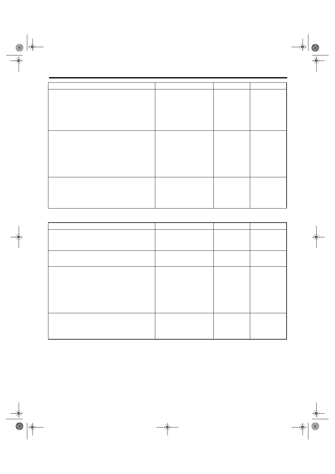
5. CHECK COMMUNICATION CIRCUIT OF FUEL ECONOMY SYSTEM

C: NOTE

For procedure of each component in the clock system, refer to the respective section.

• Clock: <Ref. to IDI-21, Clock.>

4

CHECK AMBIENT TEMPERATURE DIS-
PLAY.
1) Connect the combination meter connector.
2) Install the 3 kΩ resistance to ambient sen-
sor connector terminal.
3) Turn the ignition switch to ON.

Connector & terminal

(F78) No. 1 — (F78) No. 2:

Does the ambient temperature 
display 25°C (77°F)?

Repair the poor 
contact between 
the ambient sensor 
and harness con-
nector.

Go to step 

5.

5

CHECK AMBIENT TEMPERATURE OUTPUT 
DATA.
1) Prepare the Subaru Select Monitor kit.
2) Turn the ignition switch to ON (engine OFF) 
and run the “PC application for Subaru Select 
Monitor”.
3) On «System Selection Menu» display, 
select {Integ. unit mode}.
4) Select {Ambient Temperature}.

Does the ambient temperature 
display 25°C (77°F)?

Go to step 

6.

Replace the meter 
case assembly. 
<Ref. to IDI-16, 
Combination 
Meter.>

6

CHECK CLOCK.
1) Remove the clock.
2) Attach the ambient temperature display to 
another vehicle on which the ambient tempera-
ture display operates normally to check its oper-
ation.

Does the ambient temperature 
display 25°C (77°F)?

Replace the clock 
body.

Replace the meter 
case assembly.

Step

Check

Yes

No

1

CHECK FUEL ECONOMY DISPLAY OFF 
MODE.
Hold down the button “+” on the clock for 5 sec-
onds or more.

Does the fuel economy display 
part blink?

Go to step 

2.

Go to step 

3.

2

CHECK FUEL ECONOMY DISPLAY OFF 
MODE.
Turn the ignition switch to ON.

Is fuel economy displayed?

Clock is normal.

Go to step 

3.

3

CHECK DIAGNOSTIC TROUBLE CODE 
(DTC).
1) Prepare the Subaru Select Monitor kit.
2) Turn the ignition switch to ON (engine OFF) 
and run the “PC application for Subaru Select 
Monitor”.
3) On «System Selection Menu» display, 
select {Integ. unit mode}.
4) Select the {Diagnostic Code(s) Display}.

Is DTC detected?

Go to step 

4.

Replace the meter 
case assembly.

4

CHECK CLOCK.
1) Remove the clock.
2) Attach the fuel economy display to another 
vehicle on which the fuel economy display oper-
ates normally to check its operation.

Is the fuel economy display cor-
rect?

Replace the clock 
body.

Replace the meter 
case assembly.

Step

Check

Yes

No

IDI-16

Combination Meter

INSTRUMENTATION/DRIVER INFO

4. Combination Meter

A: REMOVAL

1) Disconnect the ground cable from battery.

2) Set  the  tilt  steering  at  the  lowest  position.  For

steering  wheel  with  telescopic  system,  pull  the

steering.

3) Remove  the  plastic  hook  (A),  and  detach  the

meter visor.

4) Remove  the  screws  of  the  combination  meter,

and pull on the meter while tipping it towards your-

self.

5) Disconnect  the  connector  in  the  rear  side  of

combination meter to remove meter.
CAUTION:

• Be careful not to damage the meter or instru-

ment panel.

• Pay  particular  attention  to  avoid  damaging

the meter glass.

B: INSTALLATION

CAUTION:

• Make  sure  the  electrical  connector  is  con-

nected securely.

• Make sure that each meter operates normal-

ly.

• When  the  combination  meter  has  been  re-

placed,  be  sure  to  perform  the  registration  of

immobilizer.

Install each part in the reverse order of removal.

C: DISASSEMBLY

1. DISASSEMBLY OF COMBINATION 

METER

CAUTION:

• Use gloves to avoid damage and getting fin-

gerprints on the glass surface  and meter sur-

faces.

• Be careful not to apply excessive force to the

trip knob.

• Be sure not to touch the meter indicator nee-

dle.

Disengage  the  tabs  (A),  and  remove  the  meter

glass  assembly  (B)  and  meter  visor  (C)  from  the

meter case assembly (D).

2. BULB REPLACEMENT

LEDs are used for all of warning lights and indicator

lights  of  combination  meters,  replace  the  meter

case assembly if faulty.

D: ASSEMBLY

Assemble each part in the reverse order of disas-

sembly.

EI-01893

(A)

IDI00375

IDI00267

(A)

(D)

(C)

(B)

IDI-17

Speedometer

INSTRUMENTATION/DRIVER INFO

5. Speedometer

A: SPECIFICATION

Since  the  meter  case  assembly  cannot  be  disas-

sembled, do not remove or inspect the speedome-

ter  alone.  (Do  not  remove  the  cover  on  the  back

surface.)

IDI-18

Tachometer

INSTRUMENTATION/DRIVER INFO

6. Tachometer

A: SPECIFICATION

Since  the  meter  case  assembly  cannot  be  disas-

sembled, do not remove or inspect the tachometer

alone. (Do not remove the cover on the back sur-

face.)


Content   ..  704  705  706  707   ..