Subaru Legacy (2005 year). Service manual - part 631


  Index      Subaru     Subaru Legacy - service and repair manual 2005 year


Search            


Content   ..  629  630  631  632   ..


Subaru Legacy (2005 year). Service manual - part 631


5AT(diag)-115

AUTOMATIC TRANSMISSION (DIAGNOSTICS)

Diagnostic Procedure with Diagnostic Trouble Code (DTC)

AN:DTC P1760 LATERAL ACCELERATION SENSOR PERFORMANCE PROB-

LEM

DTC DETECTING CONDITION:
Faulty lateral G sensor output voltage
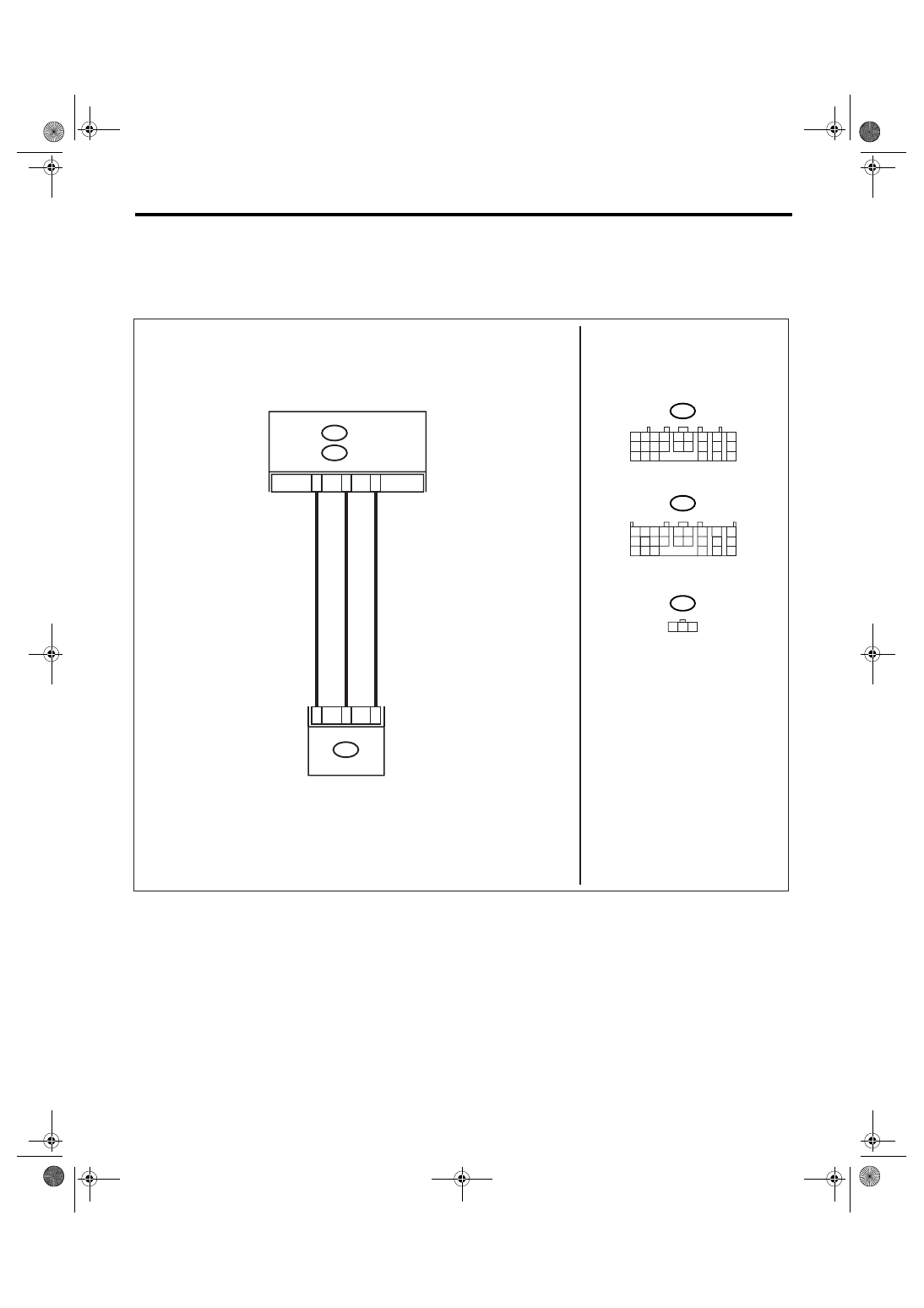
WIRING DIAGRAM:

AT-01634

A13

B54

TCM

B359

2

1

3

B5

B6

2 3

1

B54

B359

G SENSOR

1 2 3 4

10 11 12
19 20 21

13

5 6

14 15

7

8

9

16

17

18

22

23

24

B55

A:

B55

B:

1 2

7

8

9

5 6

3 4

10 11 12
19 20 21

13

14 15

16

17

18

22

23

24

A:

B:

5AT(diag)-116

AUTOMATIC TRANSMISSION (DIAGNOSTICS)

Diagnostic Procedure with Diagnostic Trouble Code (DTC)

Step

Check

Yes

No

1

CONFIRM WQUIPMENT OF VEHICLE.

Is VDC equipped with the vehi-
cle? And is there VDC OFF 
switch in the instrument panel?

Go to step 2.

Go to step 4.

2

CHECK DTC OF TCM.

Is DTC of AT CAN communica-
tion detected?

Perform the diag-
nosis according to 
DTC.

Go to step 3.

3

CHECK DTC OF ABS.

Is DTC of ABS detected?

Perform the diag-
nosis according to 
DTC of ABS

Temporary poor 
contact occurs. 
Recheck the har-
ness and connec-
tor for faulty.

4

CHECK OUTPUT OF LATERAL G SENSOR 
USING SUBARU SELECT MONITOR.
1) Select {Current Data Display & Save} in 
Subaru Select Monitor.
2) Read the Subaru Select Monitor display.

Is the value on display 2.3 — 
2.7 V when the vehicle is on a 
level?

Go to step 5.

Go to step 10.

5

CHECK OUTPUT OF LATERAL G SENSOR 
USING SUBARU SELECT MONITOR.
1) Turn the ignition switch to OFF.
2) Remove the console box.
3) Remove the lateral G sensor from vehicle. 
(Do not disconnect connector.)
4) Turn the ignition switch to ON.
5) Select {Current Data Display & Save} in 
Subaru Select Monitor.
6) Read the Subaru Select Monitor display.

Is the value on display 3.3 — 
4.3 V when lateral G sensor is 
inclined to the right to 90

°?

Go to step 6.

Replace the lat-
eral G sensor. 
<Ref. to 5AT-62, 
Lateral G Sensor.>

6

CHECK OUTPUT OF LATERAL G SENSOR 
USING SUBARU SELECT MONITOR.
Read the Subaru Select Monitor display.

Is the value on display 0.7 — 
1.7 V when lateral G sensor is 
inclined to the left to 90

°?

Go to step 7.

Replace the lat-
eral G sensor. 
<Ref. to 5AT-62, 
Lateral G Sensor.>

7

CHECK POOR CONTACT IN CONNECTOR.
Turn the ignition switch to OFF.

Is there poor contact in con-
nector between TCM and lat-
eral G sensor?

Repair the con-
nector.

Go to step 8.

8

CHECK ABSCM&H/U.
1) Connect all the connectors.
2) Perform the clear memory mode.
3) Perform the inspection mode.
4) Read the DTC.

Is the same DTC displayed?

Replace the TCM. 
<Ref. to 5AT-61, 
Transmission Con-
trol Module 
(TCM).>

Go to step 9.

9

CHECK OTHER DTC DETECTION.

Is any other DTC displayed?

Perform the diag-
nosis according to 
DTC.

Temporary poor 
contact occurs.

10

CHECK OPEN CIRCUIT IN LATERAL G SEN-
SOR OUTPUT HARNESS AND GROUND 
HARNESS.
1) Turn the ignition switch to OFF.
2) Disconnect the connector from TCM.
3) Measure the resistance between TCM con-
nector terminals.

Connector & terminal

(B54) No. 13 — (B55) No. 6:

Is the resistance 5.0 — 6.0 
k

Ω?

Go to step 11.

Repair the har-
ness connector 
between lateral G 
sensor and TCM.

5AT(diag)-117

AUTOMATIC TRANSMISSION (DIAGNOSTICS)

Diagnostic Procedure with Diagnostic Trouble Code (DTC)

11

CHECK LATERAL G SENSOR.
1) Remove the console box.
2) Remove the lateral G sensor from vehicle.
3) Connect the connector to lateral G sensor.
4) Connect the connector to ABSCM&H/U.
5) Turn the ignition switch to ON.
6) Measure the voltage between lateral G 
sensor connector terminals.

Connector & terminal

(B359) No. 3 (+) — No. 2 (

):

Is the voltage 2.3 — 2.7 V 
when lateral G sensor is hori-
zontal?

Go to step 12.

Replace the lat-
eral G sensor. 
<Ref. to 5AT-62, 
Lateral G Sensor.>

12

CHECK LATERAL G SENSOR.
Measure the voltage between lateral G sensor 
connector terminals.

Connector & terminal

(B359) No. 3 (+) — No. 2 (

):

Is the voltage 3.3 — 4.3 V 
when lateral G sensor is 
inclined to the right to 90

°?

Go to step 13.

Replace the lat-
eral G sensor. 
<Ref. to 5AT-62, 
Lateral G Sensor.>

13

CHECK LATERAL G SENSOR.
Measure the voltage between lateral G sensor 
connector terminals.

Connector & terminal

(B359) No. 3 (+) — No. 2 (

):

Is the voltage 0.7 — 1.7 V 
when lateral G sensor is 
inclined to the left to 90

°?

Go to step 14.

Replace the lat-
eral G sensor. 
<Ref. to 5AT-62, 
Lateral G Sensor.>

14

CHECK ABSCM&H/U.
1) Turn the ignition switch to OFF.
2) Connect all the connectors.
3) Perform the clear memory mode.
4) Perform the inspection mode.
5) Read the DTC.

Is the same DTC displayed?

Replace the TCM. 
<Ref. to 5AT-61, 
Transmission Con-
trol Module 
(TCM).>

Go to step 15.

15

CHECK OTHER DTC DETECTION.

Is any other DTC displayed?

Perform the diag-
nosis according to 
DTC.

Temporary poor 
contact occurs.

Step

Check

Yes

No

5AT(diag)-118

AUTOMATIC TRANSMISSION (DIAGNOSTICS)

Diagnostic Procedure with Diagnostic Trouble Code (DTC)

AO:DTC P1761 LATERAL ACCELERATION SENSOR CIRCUIT LOW

DTC DETECTING CONDITION:
• Lateral G sensor is open or output voltage is faulty. (Model without VDC)
• CAN communication malfunction. (Model with VDC)
WIRING DIAGRAM:

AT-01634

A13

B54

TCM

B359

2

1

3

B5

B6

2 3

1

B54

B359

G SENSOR

1 2 3 4

10 11 12
19 20 21

13

5 6

14 15

7

8

9

16

17

18

22

23

24

B55

A:

B55

B:

1 2

7

8

9

5 6

3 4

10 11 12
19 20 21

13

14 15

16

17

18

22

23

24

A:

B:


Content   ..  629  630  631  632   ..