Subaru Legacy (2005 year). Service manual - part 410


  Index      Subaru     Subaru Legacy - service and repair manual 2005 year


Search            


Content   ..  408  409  410  411   ..


Subaru Legacy (2005 year). Service manual - part 410


CO(H6DO)-11

COOLING

Engine Coolant

3. Engine Coolant

A: REPLACEMENT

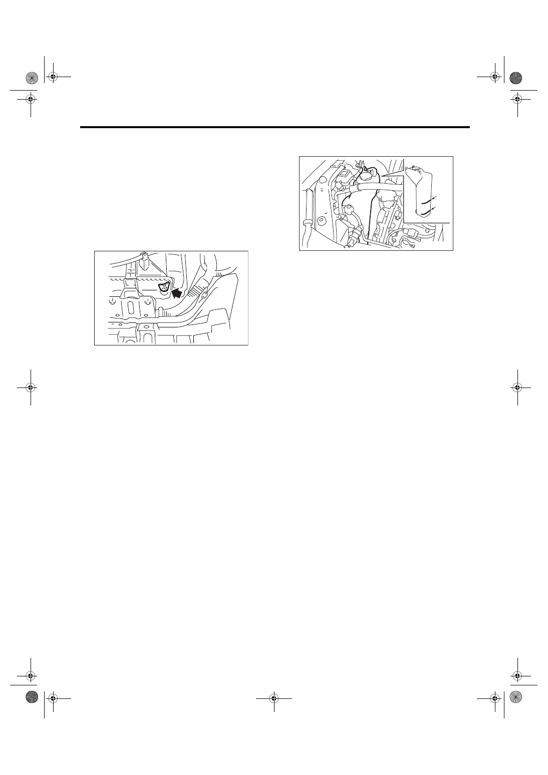
1. DRAINING OF ENGINE COOLANT

1) Lift-up the vehicle.
2) Remove the under cover.
3) Remove the drain plug to drain engine coolant
into container.

NOTE:
Remove the radiator cap so that engine coolant will
drain faster.

4) Install the drain plug.

2. FILLING OF ENGINE COOLANT

1) Pour engine coolant into the radiator up to the
filler neck position.

Coolant capacity (fill up to “FULL” level):

MT model

7.3 

2 (7.7 US qt, 6.4 Imp qt)

AT model

Model without ATF warmer

7.2 

2 (7.6 US qt, 6.3 Imp qt)

Model with ATF warmer (LHD)

7.7 

2 (8.1 US qt, 6.8 Imp qt)

Model with ATF warmer (RHD)

7.8 

2 (8.2 US qt, 6.9 Imp qt)

NOTE:
The SUBARU Genuine Coolant containing anti-
freeze and anti-rust agents is especially made for
SUBARU engine, which has an aluminum crank-
case. Always use SUBARU Genuine Coolant,
since other coolant may cause corrosion. 

2) Fill engine coolant into the reservoir tank up to
the “FULL” level.

3) Close the radiator cap and start the engine.
Race 5 to 6 times at less than 3,000 rpm, then stop
the engine. (Complete this operation within 40 sec-
onds.)
4) Wait for one minute after the engine stops, open
the radiator cap. If the engine coolant level drops,
add engine coolant into radiator up to the filler neck
position.
5) Perform the procedures 3) and 4) again.
6) Attach the radiator cap and reservoir tank cap
properly.
7) Start the engine and operate the heater at max-
imum hot position and the blower speed setting to
“LO”. 
8) Run the engine at less than 2,000 rpm until the
radiator fan starts and then stops.

NOTE:
• Be careful with the engine coolant temperature
gauge to prevent overheating.
• If the radiator hose becomes harden with the
pressure of engine coolant, air bleeding operation
seems to be almost completed.
9) Stop the engine and wait until engine coolant
temperature lowers to 30

°C (86°F).

10) Open the radiator cap. If the engine coolant lev-
el drops, add engine coolant into radiator up to the
filler neck position and reservoir tank to the “FULL”
level.
11) Attach the radiator cap and reservoir tank cap
properly.
12) Set the heater setting to maximum hot position
and the blower speed setting to “LO” and start the
engine. Perform racing at less than 3,000 rpm. If
the flowing sound is heard from the heater core, re-
peat the procedures from 8).

CO-02012

(1) FULL

(2) LOW

(1)

(2)

CO-00110

CO(H6DO)-12

COOLING

Engine Coolant

B: INSPECTION

1. RELATIONSHIP OF SUBARU COOLANT 
CONCENTRATION AND FREEZING TEM-
PERTAURE

The concentration and safe operating temperature
of SUBARU coolant is shown in the diagram. Mea-
suring the temperature and specific gravity of the
coolant will provide this information.
[Example]
If the coolant temperature is 25

°C (77°F), its specif-

ic gravity is 1.054 and the concentration is 35%
(point A), the safe operating temperature is 

−14°C

(7

°F) (point B), and the freezing temperature is −

20

°C (−4°F) (point C).

2. PROCEDURE TO ADJUST THE CON-
CENTRATION OF THE COOLANT

To adjust the concentration of coolant according to
temperature, find the proper fluid concentration in
the above diagram and replace the necessary
amount of coolant with undiluted solution of SUBA-
RU genuine coolant (concentration 50%).
The amount of coolant that should be replaced can
be determined using the diagram.
[Example]
Assume that the coolant concentration must be in-
creased from 25% to 40%. Find point A, where the
25% line of coolant concentration intersects with
the 40% curve of the necessary coolant concentra-
tion, and read the scale on the vertical axis of the
graph at height A. The quantity of coolant to be
drained is 2.1

2 (2.2 US qt, 1.8 Imp qt). Drain 2.1 2

(2.2 US qt, 1.8 Imp qt) of coolant from the cooling
system and add 2.1 

2 (2.2 US qt, 1.8 Imp qt) of the

undiluted solution of SUBARU coolant.
If a coolant concentration of 50% is needed, drain
all the coolant and refill with the undiluted solution
only.

CO-02172

60%

(1.054)

1.000

1.010

1.020

1.030

1.040

1.050

1.060

1.070

1.080

1.090

1.100

Safe  operating  temperature

Freezing
temperature

Concentration
of  coolant

Specific  gravity

of  coolant

Coolant  temperature

B

A

C

-40

(-40) (-22) (-4) (14) (32) (50) (68) (86)

( F)

(104)

-30

-20 -10

0

10

20

30

40

(77 F)

50%

40%

30%

20%

25 C

10%

C

CO-00012

10

0

1

2

3

(1.1,
  0.9)

(2.1,
  1.8)

(3.2,
  2.6)

10% 15%

25%

20%

30%

35%

40%

45%

A

20

30

40

50

Concentration  of  coolant  in  vehicie
and  quantity  to  be  drained

Quantity  of  coolant  to  be

drained    (US qt, Imp qt)

Necessary  Concentration
of  coolant

Concentration  of  coolant  in
the  vehicie  cooling  system  %

CO(H6DO)-13

COOLING

Water Pump

4. Water Pump

A: REMOVAL

1) Remove the radiator. <Ref. to CO(H6DO)-16,
REMOVAL, Radiator.>
2) Remove the V-belts.
<Ref. to ME(H6DO)-33, REMOVAL, V-belt.>
3) Remove the front chain cover.
<Ref. to ME(H6DO)-45, REMOVAL, Front Chain
Cover.>
4) Remove the timing chain assembly.
<Ref. to ME(H6DO)-47, REMOVAL, Timing Chain
Assembly.>
5) Remove the water pump.

NOTE:
When the water pump cannot be removed easier,
screw-in the bolt (A) to the screw part to remove
water pump.

B: INSTALLATION

1) Install the water pump to rear chain cover.

NOTE:
Apply engine coolant to O-ring.

Tightening torque

6.4 N

m (0.65 kgf-m, 4.7 ft-lb)

NOTE:
• Use a new O-ring.
• Apply engine coolant to O-ring to install water
pump easier.

2) Install the timing chain assembly.
<Ref. to ME(H6DO)-48, INSTALLATION, Timing
Chain Assembly.>

3) Install the front chain cover.
<Ref. to ME(H6DO)-45, INSTALLATION, Front
Chain Cover.>
4) Install the V-belts.
<Ref. to ME(H6DO)-33, INSTALLATION, V-belt.>
5) Install the radiator. <Ref. to CO(H6DO)-17, IN-
STALLATION, Radiator.>
6) Fill with engine coolant. <Ref. to CO(H6DO)-11,
FILLING OF ENGINE COOLANT, REPLACE-
MENT, Engine Coolant.>

C: INSPECTION

1) Check the water pump bearing for smooth rota-
tion.
2) Check the water pump sprocket for abnormali-
ties.

CO-02013

(A)

(A)

CO-02014

CO(H6DO)-14

COOLING

Thermostat

5. Thermostat

A: REMOVAL

1) Set the vehicle on a lift.
2) Lift-up the vehicle.
3) Remove the under cover.
4) Drain engine coolant completely.
<Ref. to CO(H6DO)-11, DRAINING OF ENGINE
COOLANT, REPLACEMENT, Engine Coolant.>
5) Disconnect the radiator outlet hose from thermo-
stat cover.

6) Remove the thermostat cover, and then remove
the thermostat.

B: INSTALLATION

1) Install a gasket to thermostat.

NOTE:
Use a new gasket.
2) Install the thermostat and thermostat cover.

NOTE:
The thermostat must be installed with the jiggle pin
facing to the up side.

Tightening torque:

6.4 N

m (0.65 kgf-m, 4.7 ft-lb)

3) Connect the radiator outlet hose to thermostat
cover.
4) Install the under cover.
5) Lower the vehicle.
6) Fill with engine coolant. <Ref. to CO(H6DO)-11,
FILLING OF ENGINE COOLANT, REPLACE-
MENT, Engine Coolant.>

C: INSPECTION

Replace the thermostat if the valve does not close
completely at an ambient temperature or if the fol-
lowing test shows unsatisfactory results.
• Inspection method
Immerse the thermostat and a thermometer in wa-
ter. Raise water temperature gradually, and mea-
sure the temperature and valve lift when the valve
begins to open and when the valve is fully opened.
During the test, agitate the water for even temper-
ature distribution. The measured value should
meet the specification.

NOTE:
• Leave the thermostat in the boiling water for
more than five minutes before measuring the valve
lift.

(A) Thermostat cover

(B) Thermostat

CO-02015

(A)

(B)

CO-02164

(A) Thermostat cover

(B) Thermostat

(C) Gasket

(D) Jiggle pin

(D)

(A)

T

(B)

CO-02165

(C)


Content   ..  408  409  410  411   ..