Content .. 1031 1032 1033 1034 ..
Subaru Legacy (2005 year). Service manual - part 1033
LAN(diag)-11
LAN SYSTEM (DIAGNOSTICS)
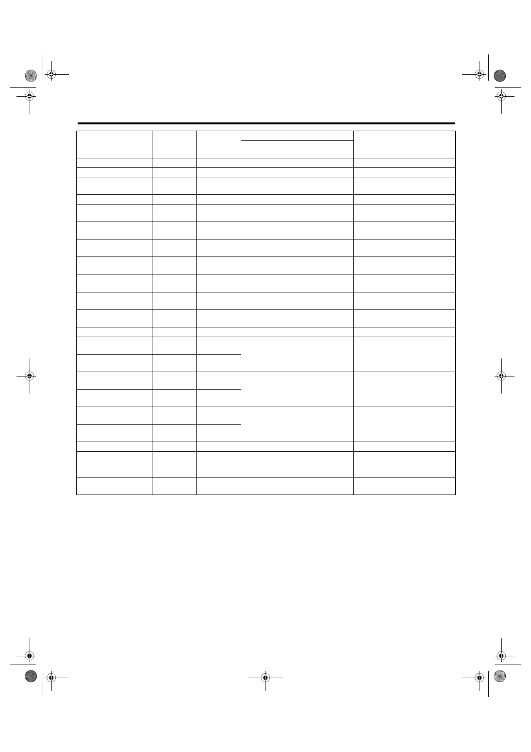
Control Module I/O Signal
Rear wiper switch (INT)
B281
C18
Less than 1
Ω
Rear wiper switch ON
Rear washer switch
B281
C27
Less than 1
Ω
Rear washer switch ON
Rear wiper power sup-
ply
B280
B21
10 — 13 V
Rear wiper ON output
B280
B1
10 — 13 V
Rear wiper switch ON
Rear wiper return
B280
B8
Less than 1
Ω
B1 — B8 less than 1
Ω
At wiper reversing
Room light output
B280
B3
Less than 1
Ω
When LOCK, UNLOCK with key-
less entry
Key ring illumination
output
B280
B4
Less than 1
Ω
Ignition key removed, driver’s
door open
Turn hazard output
B280
B12
Less than 1
Ω
When operating keyless entry
answer back
Immobilizer pilot light
i84
A33
Less than 1
Ω
At ignition key removed, immobi-
lizer operating
Alarm control ECM (EK
model)
B280
B11
Serial communication
Security horn output
(Except for EK model)
B280
B11
Less than 1
Ω
At security horn output
Keyless communication
i84
A9
2 — 10 V
At keyless entry signal received
High-speed CAN circuit
(Hi)
B280
B20
Between B20 — B30
Serial communication
At communicating (sending and
receiving)
High-speed CAN circuit
(Lo)
B280
B30
Low-speed CAN circuit
1 (Hi)
i84
A26
Between A25 — A26
Serial communication
At communicating (sending and
receiving)
Low-speed CAN circuit
1 (Lo)
i84
A25
Low-speed CAN circuit
2 (Hi)
B280
B26
Between B25 — B27
Serial communication
At communicating (sending and
receiving)
(Model with auto A/C)
Low-speed CAN circuit
2 (Lo)
B280
B27
Immobilizer antenna
B281
C20 — C21
Serial communication
Immobilizer communi-
cation (Main)
B280
B18
(Back-up
B28)
Serial communication
Subaru Select Monitor
communication
B280
B19
Serial communication
Description
Connector
No.
Terminal No.
Signal (V or
Ω)
NOTE
Ignition switch ON
(engine OFF)