Subaru Legacy (2005 year). Service manual - part 1027


  Index      Subaru     Subaru Legacy - service and repair manual 2005 year


Search            


Content   ..  1025  1026  1027  1028   ..


Subaru Legacy (2005 year). Service manual - part 1027


IM(diag)-13

IMMOBILIZER (DIAGNOSTICS)

Diagnostics Chart for Immobilizer Indicator Light

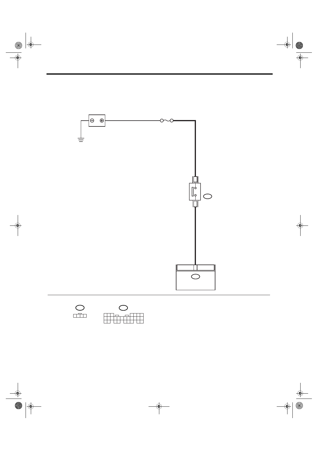
2. CHECK KEY SWITCH CIRCUIT.

WIRING DIAGRAM:

IM-00078

B350

KEY WARNING
SWITCH

B281

BODY INTEGRATED

MODULE

BATTERY

M/B No.14

C7

3

4

C:

5 6 7

8

2

1

9

4

3

10

24

22 23

25

11 12 13 14 15

26

27 28

16 17 18 19

20 21

B281

C:

B350

1 2 3 4

IM(diag)-14

IMMOBILIZER (DIAGNOSTICS)

Diagnostics Chart for Immobilizer Indicator Light

Step

Check

Yes

No

1

CHECK POWER SUPPLY CIRCUIT.
1) Disconnect the harness connector from key 
warning switch.
2) Turn the ignition switch to “ACC” or “LOCK” 
(with key inserted).
3) Measure the voltage between key warning 
switch harness connector terminal and chassis 
ground.

Connector & terminal

(B350) No. 3 (+) — Chassis ground (

):

Is the voltage more than 10 V? Go to step 2.

Check the harness 
for open or short 
circuit between 
key warning switch 
and fuse.

2

CHECK KEY WARNING SWITCH.
1) Insert the ignition key to ignition switch. 
(OFF or ACC)
2) Measure the resistance between key warn-
ing switch terminals.

Connector & terminal

No. 3 — No. 4:

Is the resistance less than 1 
Ω?

Go to step 3.

Replace the key 
warning switch.

3

CHECK KEY WARNING SWITCH.
1) Remove the ignition key from ignition 
switch.
2) Measure the resistance between key warn-
ing switch terminals.

Connector & terminal

No. 3 — No. 4:

Is the resistance more than 1 
M

Ω?

Go to step 4.

Replace the key 
warning switch.

4

CHECK HARNESS BETWEEN KEY WARN-
ING SWITCH AND BODY INTEGRATED 
MODULE.
1) Disconnect the harness connector from key 
warning switch.
2) Disconnect the harness connector from 
body integrated module.
3) Measure the resistance between key warn-
ing switch harness connector terminal and 
body integrated module harness connector ter-
minal.

Connector & terminal

(B350) No. 4 — (B281) No. 7:

Is the resistance less than 10 
Ω?

Replace the body 
integrated module 
<Ref. to SL-44, 
Body Integrated 
Module.>
 and 
replace all the igni-
tion keys (includ-
ing transponder). 
Execute the regis-
tration procedure 
next. Refer to 
“IMMOBILIZER 
TEACHING 
OPERATION 
MANUAL”.

Repair the har-
ness between key 
warning switch 
and body inte-
grated module.

IM(diag)-15

IMMOBILIZER (DIAGNOSTICS)

List of Diagnostic Trouble Code (DTC)

9. List of Diagnostic Trouble Code (DTC)

A: LIST

1. ENGINE ECM

NOTE:
Perform the engine DTC when the DTC except for immobilizer DTC is detected. <Ref. to EN(H4SO 2.0)(di-
ag)-64, List of Diagnostic Trouble Code (DTC).> <Ref. to EN(H4SO 2.5)(diag)-69, List of Diagnostic Trouble
Code (DTC).> <Ref. to EN(H4DOTC)(diag)-62, List of Diagnostic Trouble Code (DTC).> <Ref. to
EN(H6DO)(diag)-66, List of Diagnostic Trouble Code (DTC).>

DTC

Item

Contents of diagnosis

Index No.

P0513

Incorrect Immobilizer Key

Incorrect immobilizer key (Use of 
unregistered key in body integrated 
module)

<Ref. to IM(diag)-17, DTC P0513 INCOR-
RECT IMMOBILIZER KEY, Diagnostic Pro-
cedure with Diagnostic Trouble Code 
(DTC).>

P1570

Antenna

Faulty antenna

<Ref. to IM(diag)-18, DTC P1570 
ANTENNA, Diagnostic Procedure with Diag-
nostic Trouble Code (DTC).>

P1571

Reference Code Incompatibility

Reference code incompatibility 
between body integrated module 
and ECM

<Ref. to IM(diag)-20, DTC P1571 REFER-
ENCE CODE INCOMPATIBILITY, Diagnos-
tic Procedure with Diagnostic Trouble Code 
(DTC).>

P1572

EGI — Immobilizer Communi-
cation (Except Antenna Circuit)

Communication failure between 
body integrated module and ECM

<Ref. to IM(diag)-21, DTC P1572 IMM CIR-
CUIT FAILURE (EXCEPT ANTENNA CIR-
CUIT), Diagnostic Procedure with Diagnostic 
Trouble Code (DTC).>

P1574

Key — Immobilizer Communica-
tion

Failure of body integrated module to 
verify key (transponder) ID code

<Ref. to IM(diag)-24, DTC P1574 KEY COM-
MUNICATION FAILURE, Diagnostic Proce-
dure with Diagnostic Trouble Code (DTC).>

P1576

EGI Control Module EEPROM

ECM malfunctioning

<Ref. to IM(diag)-25, DTC P1576 EGI CON-
TROL MODULE EEPROM, Diagnostic Pro-
cedure with Diagnostic Trouble Code 
(DTC).>

P1577

IMM Control Module EEPROM

Defective body integrated module

<Ref. to IM(diag)-25, DTC P1577 IMM CON-
TROL MODULE EEPROM, Diagnostic Pro-
cedure with Diagnostic Trouble Code 
(DTC).>

P1578

Meter Failure

Reference code incompatibility 
between body integrated module 
and combination meter

<Ref. to IM(diag)-25, DTC P1578 METER 
FAILURE, Diagnostic Procedure with Diag-
nostic Trouble Code (DTC).>

IM(diag)-16

IMMOBILIZER (DIAGNOSTICS)

List of Diagnostic Trouble Code (DTC)

2. BODY INTEGRATED MODULE

NOTE:
• Immobilizer system of 2.5 L EC, EK model and 3.0 L model perform the starter relay control. When the
body integrated module detect the inconformity of reference code, immediately out put the starter relay cut
signal to ECM, and then ECM stop the starter relay operation. In this case, engine does not start, and DTC
is not recorded in ECM. Check that the engine does not start on the DTC of body integrated module.
• DTC B0402 is recorded as freeze frame data when the ignition switch is turned to OFF. When trying to start
the engine with unregistered immobilizer key, DTC is not displayed on Subaru Select Monitor immediately.
Turn the ignition switch to OFF once and turn to ON again before checking DTC. At this time (when turning
the ignition switch to ON again), be careful that the DTC is displayed as freeze frame data even with the reg-
istered immobilizer key.

DTC

Item

Contents of diagnosis

Index No.

Relation between ECM and 

DTC

B0401

M collation NG

Reference code incompatibil-
ity between body integrated 
module and combination meter

<Ref. to IM(diag)-25, DTC 
P1578 METER FAILURE, Diag-
nostic Procedure with Diagnos-
tic Trouble Code (DTC).>

P1578

B0402

Immobilizer Key colla-
tion NG

• Incorrect immobilizer key 
(Use of unregistered key in 
body integrated module)
• Faulty antenna

<Ref. to IM(diag)-17, DTC 
P0513 INCORRECT IMMOBI-
LIZER KEY, Diagnostic Proce-
dure with Diagnostic Trouble 
Code (DTC).> <Ref. to IM(diag)-
18, DTC P1570 ANTENNA, 
Diagnostic Procedure with Diag-
nostic Trouble Code (DTC).>
 or 
<Ref. to IM(diag)-24, DTC 
P1574 KEY COMMUNICATION 
FAILURE, Diagnostic Procedure 
with Diagnostic Trouble Code 
(DTC).>

• P0513
• P1570
• P1574

B0403

E/G request NG

Communication failure 
between body integrated mod-
ule and ECM

<Ref. to IM(diag)-21, DTC 
P1572 IMM CIRCUIT FAILURE 
(EXCEPT ANTENNA CIR-
CUIT), Diagnostic Procedure 
with Diagnostic Trouble Code 
(DTC).>

P1572


Content   ..  1025  1026  1027  1028   ..